Updated:
14-Jan-04
The PhonoDude RIAA
Tube Amplifier
PCB Version...
Introduction and design
ideas
 This
project has been in the pipe for a very long time already. Why? Actually after I
have built the "old" DD-PRE I realized that
this amp could benefit from a few improvements and it should be more easy to
build this amplifier as a real stand alone unit. For the real fans (who read all
of my Site :-) will remember, that the 300K Volume rotary switch is active part
of the passive RIAA correction !!! This could be a source of potential problems,
specially when driving a PRE-AMP through an Interlink !! Also the RIAA amp was
hard to get totally quiet. I was playing with some ideas for years to have a
first stage without a Rk, so Ugs=0 Volt.... Very unusual for a Tube design, as
you will have grid current, so it was still hanging around in my mind for a
while. Why would you do this ?? 2 reasons: The impedance in the input circuit is
related to the noise level you will get and for HUMM purpose, it would be better
to have the cathode hard wired to the ground. Oh, a 3rd reason would be that no
Rk-decoupling-capacitor is needed at this point where the signals are so small
and sensitive ....
This
project has been in the pipe for a very long time already. Why? Actually after I
have built the "old" DD-PRE I realized that
this amp could benefit from a few improvements and it should be more easy to
build this amplifier as a real stand alone unit. For the real fans (who read all
of my Site :-) will remember, that the 300K Volume rotary switch is active part
of the passive RIAA correction !!! This could be a source of potential problems,
specially when driving a PRE-AMP through an Interlink !! Also the RIAA amp was
hard to get totally quiet. I was playing with some ideas for years to have a
first stage without a Rk, so Ugs=0 Volt.... Very unusual for a Tube design, as
you will have grid current, so it was still hanging around in my mind for a
while. Why would you do this ?? 2 reasons: The impedance in the input circuit is
related to the noise level you will get and for HUMM purpose, it would be better
to have the cathode hard wired to the ground. Oh, a 3rd reason would be that no
Rk-decoupling-capacitor is needed at this point where the signals are so small
and sensitive ....
So, what happened
then that there is real result now??? End of 2002 I brought up the
discussion with Audio Partner in Crime: Triode
Dick... I told him about the Ugs=0Volt design idea.
With his extreme knowledge of almost every tube in the universe (may be slightly
overdone, but close... -:) he immediately came up with the 5755 Tube. A kind of
ECC83 (not the same pinning !!!) so looked very suitable for this purpose, but
the best was, that according to Dick this Tube was designed to work at zero Volt
Ugs... A pity that in the datasheets you will find nothing specified
about this application (??) so I decided to do some testing, what else would you
expect from me ?? The outcome was great, at 0Volt the 5755 was drawing in the
range of 20-50nA (nano-ampere !!) I compared this with a few 5961
tubes I used in the DD-PRE and these were in the range of 1uA !! This could lead
to a significant off-set voltage for the pick-up element. Last but not least: NO
Rk reduces greatly the output impedance of this stage, which is good for the
RIAA curve and the PSSR is also much higher, which again is preventing noise and
HUMM from the power supply to be induced
On the other
subject, I thought it would be better to have the whole RIAA correction between
2 stages, so the output impedance would be very low, allowing for driving
cables and volume pots easily. Now things were relatively easy. I set up a study
design with 2 MU-Followers and a passive RIAA filter (again also including the
50kHz pole !!) and then NOTHING happened.............. I was so busy with work
and other projects, I just could not put my self to work to built
something to replace some thing which was playing well already..... Again,
Triode Dick was the saving angel, hahaha !! As you can read (if you can read
dutch :-) on his Site, he was in a need for building a new phonostage
as well,
to replace the Scratch design. Also the scratch plays very nice, but was
suffering from a not optimal situation as well: The output impedance of the
first (anode resistor loaded) stage is INCLUDED in the RIAA correction. so no
constant results possible and your RIAA will change over time.... So Dick took
up my design study, built it, improved the 2nd Stage, tested the RIAA curve and
came up with the "final" components value and told me about the result
!!! He was more than satisfied (now an understatement
:-) with the result. I was enthusiastic as well and decided to make a PCB
available, so this absolute TOP
RIAA amplifier could be made available for a wide public !! Both Dick and I
built the PCB versions and it at both sides every thing worked immediately, no
bugs no issues. Also my RIAA curves were ok the first time !!! (I did use 1%
metal film and selected the capacitors of course)
Well now you
know everything about how this successful
project saw the light, so lets go into some detail how it works, measures and
sounds........
Project
Description
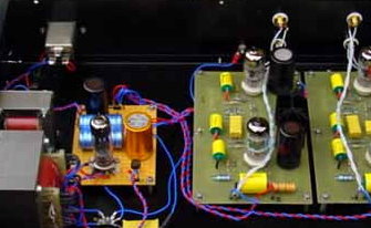
Below is the circuit of everything which is
ON the Printed Circuit Board. You can click on it for more resolution. You can
clearly recognize the MU-Follower configuration of the input and output stage
Lets start at the left....... minimized input
circuit with no grid resistor (extra noise !!) no
Rk and no Ck. The 47k is the preferred load for a
MD cartridge, but feel free to do whatever you like here.... C2 is in the signal
path and should be top quality, I used Auricaps, as they are very neutral. Most
close to a "wire" in my humble opinion. The output resistance
from this stage is only 1k7, so the influence on the RIAA circuit is minimal.
At the output of this stage the passive RIAA
Filter is DC coupled. Normally you don' see this, why did I ?? Very simple,
something a lot of designs lack is to take into contribution, the voltage dividing
between the Couple C and C3/C4, this will cause a drop in the lowest frequencies.
The solution is so simple: Put the couple C after the RIAA network !! The 3
colors are representing 3 of the poles above 50Hz of the filter and exactly with these 3
resistors you can adjust the RIAA curve when the components
are not 100% on value (not always you can select) In the pdf document you can
download, there is instruction how to do this !! Read this as the sequence is
important....
Click on the
image for a high resolution image on your screen. (click
here for the full PDF document)

The second
stage is less critical and is just an amplifying buffer stage, presenting almost
NO load to the filter and providing a LOW impedance to the next stage or
interconnect cable... What else is provided on the PCB ??? To make things easy,
I have implemented a Regulator solution for the filaments,
This should be fed with a "raw" DC voltage of minimum 15 Volt. Maximum
is not so critical, but I suggest to stay below 20 Volt, to minimize the heat
development on the Cooling sink. Do not forget to trim the voltage on 12 to 12.6
Volt !! This is actually the only thing you have to do, to make the PhonoDude
work..... Last thing: Both Stages are DC decoupled by R6/18 and C1/6. The
PCB is designed to take JJ 47uF or 100uF, but of course you can take what ever
you want..... Here is a tweaking possibility as well for personal preference etc
etc.....
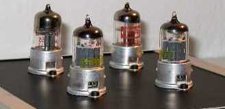
One last
important note: For lay-out reasons I have connected the 2 tubes filaments in
series.... This works fine as the filament
currents from the 5755 and 5751 are almost the same. BUT: if you use a ECC83,
you need to compensate for the approximately 40mA
lower current then the 5751. Therefore you must solder at the bottom of the PCB
between pin4/5 and pin9 a resistor of 150Ohm (6.3 Volts / 40mA). 120 is
fine as well, you can check with a multimeter the balance between the 2 tubes
if you like to be very precise ...... And for the
extremists,
mount a 200Ohm trimmer and trim exactly at 6.3 Volts across the trimmer :-)
Power dissipation is only (6.3V x 6.3V / 150Ohm)
1/4 Watt, so no issue...
What about
the power supply ??????
Thanks to the
PCB, the Power supply can be very simple, or just as simple as you want it to be
. I have tested the PhonoDude with a 305 Volt power supply, but this is NOT
critical !!! Thanks to the MU-follower the stage will work with almost
everything between 150-400 Volt. But 300 Volts appears to be a good middle
way..... Any thing with a stable 300V DC will work, you can use Tubes, Silicon
diodes, Chokes etc. I have tested with a regulated Tube power supply and with a
simple 1N4007 with only a 200uF capacitor !! You could hear the difference, but
they were small and both sounded good.
Click on the
image for a high resolution image on your screen. (click
here for the full PDF document)
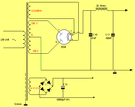
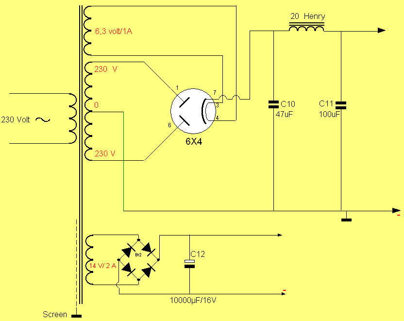
Never the
less, here above, you see a simple tube rectifier solution. Why? Because it is
so simple and is definitely better then the 1N4007
solution Also AE-Europe is
delivering a complete set with transformer and the 6X4 tube, DIY Life never was
SOOOOOO easy....... For the filaments: only a diode bridge and large filter cap
is necessary. Everything between 2.200 and
10.000uF will do. As they are so cheap these days, I would take a 10.000uF :-)
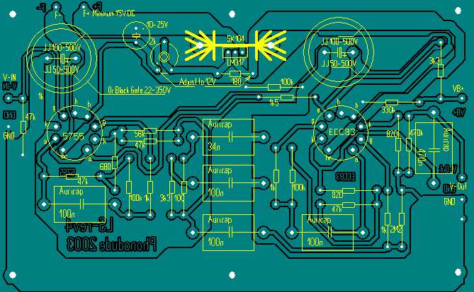
The PCB:
Not
much to say about to be honest .... If you click on the image, you will get a
high resolution, printer friendly version, which can be used when mounting the
PCB. All values are drawn in, so should cause no problems. The same version is
in the pdf document, so choice enough.... The PCB is taking the small kind of
Noval Tube holders, where the pins are straight beneath the pins of the tube so
make sure to buy the right ones. You also have versions where the pins are bent
to the outside, this will not fit !! Also AE-Europe is offering the right
PCB-tube holders... If you are not using isolated distance holders to mount the PCB,
make sure to cut a little copper round the holes (with a drill or so) and put
isolation rings under the PCB. You don't want ground loops,
don't you ??
Click on the
image for a high resolution PRINTABLE image on your screen. (click
here for the full PDF document)
Measurements
The PhonoDude
does its work without fine tuning, but if you have the means, it is
always interesting to check how good the curve is.... Of course I wanted to test
my Prototype my self........ Not much work was needed :-).
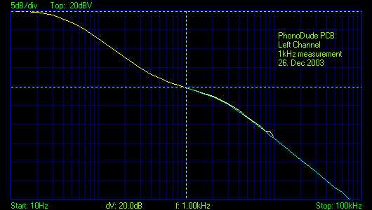

Above the
1kHz measurement. According to the official RIAA curve, this needs to be -20dB
versus the low frequencies. With 20.2 and 20.2 I am more then
satisfied !
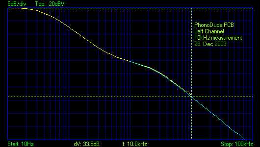
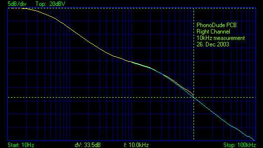
The same
good result for the 10kHz level. As you can see I do the RIAA "run" 2
times, and this is a combined curve. This is done to make optimum use of the resolution
of the Digital Scoop I am using....
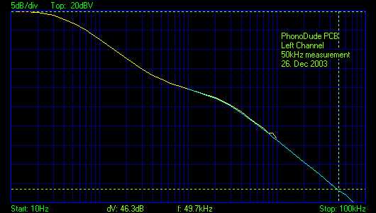
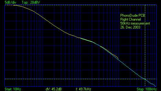
At 50kHz I
am a little bit off. This could be tuned with R10, but as
this is no critical point I just let it this way. Perfectionists would slightly
change the 100 Ohm resistor of course :-)

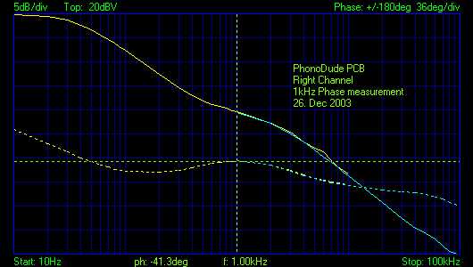
Another way
of measuring the balance of the filter. Basically the phase of a well balanced
system will show a peak at 1kHz and this peak should be the same as the phase at
50Hz From the phase measurement above you see that this is the case for both channels.
Also the channels are identical !! Don't try this with a anode loaded
amplifier ..... :-)
Listening
I have tried the PhonoDude in a kind of test application in my
stereo
system. Source was the LINN LP12/EKOS/LINGO/Ortofon-Jubilee combination with the Sowter 1:10
Step up transformers. A chassis will be constructed
in January/February and will be hard wired, as I will do some tweaking with
components..... Any way, the results were astonishing, given the totally open
set up !! At the floor you see another project, which is still in pre-publishing
stage, the "TubeRex". This is a high end Tube regulated Power
supply. I could not resist the opportunity
to do a double test ;-)...!
First the sound was too sharp, so I let it alone and "burn-in" for 2
days.... Good !!! That helped !! Now everything was in place.
I have listened to all kind of music, classic, pop, jazz and in all instances
the PhonoDude performed better then the "old" DD-PRE RIAA amp. They are
both very good, but the PhonoDude is presenting more sound stage, more detail, more
air around everything. The old RIAA is more laid back, less revealing
acoustics..... The PhonoDude is truly the best RIAA I have been hearing so far
!!!
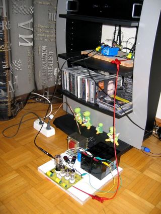
The test Situation, far from
ideal, but still great performance !!!
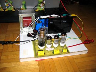
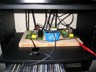
At the left the TubeRex.....
at the right the 2 PhonoDude PCB's.... with the blue transformer for the raw DC
filament Supply
Last words on the effect of the power supply... I had 2 power supplies to test,
the high end Tube regulated version and an extremely simple Diode-C supply. The
differences are not huge, but if you listen through I have noticed that the
regulated supply is causing more air in the sound stage and surprisingly high
amounts of low level detail !!! This was making the instruments and vocals sound
very very natural !!! Timbre, little collateral
sounds, air, etc, etc. The effect is small, but absolutely addicting !!! I
will do more tests with different combinations,
but that is for later this year. At this moment the PhonoDude is a working
completed system, which plays at stunning heights
:-)
Conclusions !!
It took a while, but again, this project proved me, that the Internet is
helping our Hobby to unparalleled levels of joy..... The co-operation between
Dick and my self have made the result of this project possible. Again, and now
we get boring again, WITHOUT the use of proper T&M equipment, the result
would not have been as it is now !!!! But This is
only necessary for your OWN design. If you use
this set up, you only need a multimeter and some hobby experience. Are
there any next steps? Yes, I will do tests with different power supplies and
experiment with the JJ Caps, replacing them with HIGH END Black Gates or removed
them totally etc etc... Just want to know what the effect
will be. Of course you will read about this sometime in the tweak
of the week :-)
Want to built your own PCB
version ???
If you do, things will be very easy. AE-Europe is selling most of the
components and the PCB's are for sale from my Site. Never things more easy !
As the 5755 is not always easy to get, I joint the purchase of a large volume of
these tubes. I am offering these as a package with the PhonoDude PCB's. In order
to get no unbalance between PCB's and Tubes I kindly ask you to respect
this.
This also helps me making investments like buying larger volumes and having
start costs for the PCB. Thanks for your understanding... Of course, if you
insist (may be you have hundreds of the 5755 at home :-) I can also send the PCB
only, but the only reduction will be the shipping cost, as I can put PCB's
in an
envelope in stead of using a small box (Tubes in an envelope might not proof to
be such
a good idea, eh?)
Check the link below for more details.....
Check
at the DD Sales Page for more Information
Below you will find a table
with all parts which are ON the PCB.
So if you want a stereo version, you need 2 times this partlist ;-)
| Part
Indicator |
Part
description |
Qty
|
| R1,
R5, R17 |
47k-1/4
Watt, carbon |
3 |
| R2,
R11, R13 |
1k
- 2k2 1/4 Watt, carbon |
3 |
| R3,
R14, R22 |
100k
1/4 Watt, carbon |
3 |
| R4 |
680-1/4
Watt, carbon |
1 |
| R6 |
1k5-1/4
Watt, carbon |
1 |
| R7 |
3k3-1/4
Watt, metal |
1 |
| R8 |
47k-1/4
Watt, metal |
1 |
| R9 |
56k-1/4
Watt, metal |
1 |
| R10 |
100-1/4
Watt, metal |
1 |
| R12 |
2M2-1/4
Watt, carbon |
1 |
| R15,
R16 |
820-1/4
Watt, carbon |
2 |
| R18 |
3k3-1/4
Watt, carbon |
1 |
| R19 |
470k-1/4
Watt, carbon |
1 |
| R20 |
180-1/4
Watt, carbon |
1 |
| R21 |
330k-1/4
Watt, carbon |
1 |
| P1 |
2k
trimmer one turn 10mm |
1 |
| C1,
C6 |
47uF-100uF
ELCO JJ 500V |
2 |
| C2,
C3, C5, C7 |
100nF
Auricap 450 Volt |
4 |
| C4 |
33nF
Auricap 450 Volt // 1nF MKP |
1 |
| C8 |
470nF
- 1uF Auricap 450 Volt |
1 |
| C9 |
10uF
/ 25V radial ELCO |
1 |
| IC1 |
LM317,
voltage regulator |
1 |
| Pins |
1mm
Soldering Pins |
~ 10
|
| SK104 |
Heat
Sink for PCB mounting |
1 |
| Noval
Tube Holder |
Noval
Tube Holder for PCB mounting |
2 |
| PhonoDude
ver. 4 |
PhonoDude
PCB board |
1 |
Example of how Triode Dick
built a complete RIAA Phono Amplifier chassis with the PhonoDude PCB:
Beside the hard wired version, Dick also built a complete
chassis for a good friend. Just have a look at the pictures as these will tell
the story for itself. It never have been more easy to built a phono tube
amplifier I think :-)
Click the picture below to
get the other images (or here)
Example of how Doede built a
hard wired PhonoDude:
And now my own hard wired version......... Just have a look at the pictures as these will tell
the story for itself.
Click the picture below to
get the other images (or here)
Happy building, listening
AND testing.......
Doede
IMPORTANT:
The information provided on this page is intended as guide for DIY activities and
therefore free to copy and or publish. If any one wishes to use any of the information
from my WEB site, please make sure to refer and footnote to my URL Link as source! Doede
Douma