Updated:
04-Oct-01
Doede's Tube Stories...
New Project: the
DDPRE1, a complete new PRE AMP with Phono Stage
With all the tweaks and
changes I have been making on the DDDAC Tube Stage, I have improved the sound to such an
extend, that I crossed the line !! Which line ?? The line where my analog reference
was….. The LINN with Ortophon Jubilee. The old ECC83 SRPP Phono stage with solid
state power supply and too much Wima C’s in it, is becoming the bottleneck. Well good
news, then there is a good reason, to start building again !! For those who gave a closer
look at the DDDAC, have noticed already that it is a bit FULL, ahem… So I made the
decision to remove the Tube sage from the DAC en build something new. The schematics, you
can find at the download area…. The design basics are:
- Phono consists of 2 MU stages with 6SL7 (high gain, low noise)
- Passive RIAA in 2 stages
- Line stage as before, with options to use 30-look alike (like Philips), 27, 227, 56 and
76 as well !
- Double power supply with ACS MKP in Oil C’s using AZ11 meshplate
- Combination of Hovland and PIO signal coupling C’s in the Phono stage and PIO/PIO
in the Line stage (phono deserves a bit bite...)
- Stepped attenuator and no Volume control for the DAC……..
That last item was a ingenious tip from Ward, (thanks Ward !). As the Line Stage will
move from one case to another, I will leave the rotary switch on the DDDAC, but now with a
set of R I/V resistors (and one –20dB attenuator) The whole idea is, that the PCM63
will only deliver Output voltage as needed, resulting in maximum linearity at any given
sound level as well lowest possible Output resistance. Of course there is a limit, since
the Sowter transformers cannot drive any unlimited capacity…. The limit is on driving
aprox 100pF. So make sure if you use a setup like this to use a low C interlink. I will
make one my self from silver wire. The capacitance will be below
25pF, so low enough. You can get the version 3.0 from the download
page
All parts are ordered, so I only need to build it…… and you will be able to
read about it:
Update August 26th
Well, I had a good reason to have some delay with this project. This reason is now
playing great music in my living room. I'm sure you have been reading about Golidav
already..... But, time passes on and I felt it was time again to start some building. This
time I will (try to...) update this page every time with the different steps of the
construction. Today the most important one: the mechanical lay-out and making a stencil
again for the drilling of the holes. Why important? very simple, I do not like DIY
amplifiers on a piece of MDF board..... The eyes want to be pleased as much as the
ears....... By the way, I used the same drawing elements I created already for the
GOLIDAV, so it took me less than an hour to draw the stencil. This is easily gained back
when drilling becomes SO EASSSSYYYYYY...... and NO MISTAKES !!!
Actually the DDPRE1 is a double mono AMP in one 19" Rack. I have chosen the lay out
in such a way, that the power supply is as far as possible from the signals and the
connections are following a logical path, so resulting in short connections. I also did
not forget to make it nicely symmetrical and use all the space equally. The Rack is a
standard, simple black metal rack from Conrad Electronics (aprox 70DM, so no extravagant
"High-End-Audio-Shop-Prices...)
. 
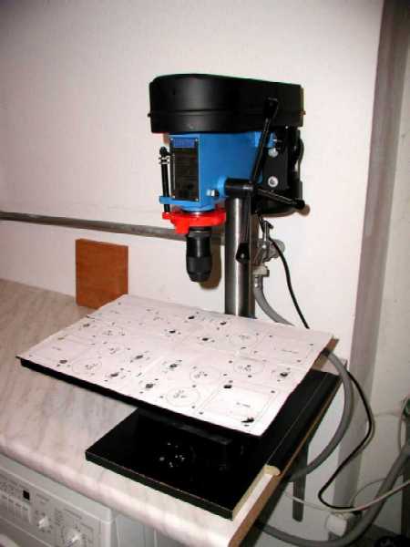
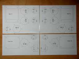
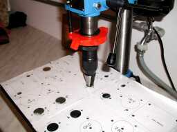
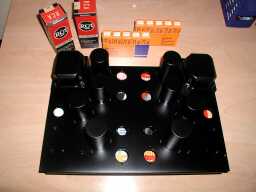
At the left the Stencil. The drawing does not fit on one A4, but I print 4
times from every corner and cut off the rest, leaving me with 4 pieces of the puzzle. With
some tape, I secure the paper to the top-panel of the rack. At the right picture, the
stencil in action with the column drilling machine. You know what? DIY is much more fun
with the right tools..
Update August 30st
I thought I had an Electronics hobby....... but no amplifier building without the
mechanical work !! Though, this is one of the nicer tasks..... What you are doing here is
what the eye will see. If you do your best here and work precise and take your time, the
long life result will always make you feel good (and proud!). The other way round, you
might save time, But later on you need that to explain all relatives and friends, that
handmade is always not that smooth and symmetrical...... Well, I don't like all this
justifying and I want to harvest compliments from the ones who sees my "brew"
So, I like to make it as professional as possible.
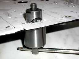
After drilling all the holes with a
3.5 mm drill, I drill again every hole to the exact diameter they need to be. Than the
holes are cut out with one of the hole punchers, I have a set with round diameters, 15,
20, 25 and 30mm. If the hole needs to be 28, I take the 25 and use the conical drill from
the right picture. Don't do it by hand !! the hole will become elliptical or just ugly
(remember the eye ??)
It might seems a lot of work, but
with the stencil you can really keep on working just very relaxed, without checking and
checking and checking and checking..... I needed 2 evenings of approximately 2
hours. As you can see the transformers are mounted also. Next step will be to mount the
Capacitors. Than it will be sprayed 2 times and than it ...... and than it .....and than
it .....and than it .....
Update September 5th
Before the Capacitors are mounted, make sure to prepare them with sandpaper. When they
are already mounted, it will be much more difficult. Ofcourse the Chassis must be sprayed
with one layer of primer first. More work, but lengthen the life of your top coating.
After 24 hours I sprayed 4 layers of black paint. between layers wait approximately 3
minutes. The result is ofcourse not like your car; there will be always dust particles on
the paint, but from a (small) distance it looks good enough.....
Before ...
and
...
After
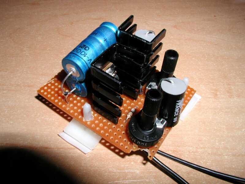
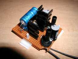 Hey! what is
that little printed circuit at the right? I thought this was the old fashioned hardwiring
/ Chassis kind of work? Yes it still is, but the Triode #30 filament works best on a
"Current Source" supply. In stead of supplying a fixed voltage, you feed the
filament with a constant current. In this case 60mA. To keep things simple, I built it up
on a piece of standard pertinax with rastered holes. The current source circuit is in the DDPRE2.PDF file. The basic function is very simple. From the
12 Volt tap from the mains TX, a rough 18Volt supply is made by the rectifier and the
filter cap of 2.200uF. The first LM317 delivers a steady and clean voltage (adjust it at
aprox 9 Volt) for the next LM317; the actual current source. With the 100 Ohm trimmer you
can adjust the current to 60mA. I already fixed them with a multimeter on 60mA. When the
amp is in operation, I will adjust finally.
Hey! what is
that little printed circuit at the right? I thought this was the old fashioned hardwiring
/ Chassis kind of work? Yes it still is, but the Triode #30 filament works best on a
"Current Source" supply. In stead of supplying a fixed voltage, you feed the
filament with a constant current. In this case 60mA. To keep things simple, I built it up
on a piece of standard pertinax with rastered holes. The current source circuit is in the DDPRE2.PDF file. The basic function is very simple. From the
12 Volt tap from the mains TX, a rough 18Volt supply is made by the rectifier and the
filter cap of 2.200uF. The first LM317 delivers a steady and clean voltage (adjust it at
aprox 9 Volt) for the next LM317; the actual current source. With the 100 Ohm trimmer you
can adjust the current to 60mA. I already fixed them with a multimeter on 60mA. When the
amp is in operation, I will adjust finally.

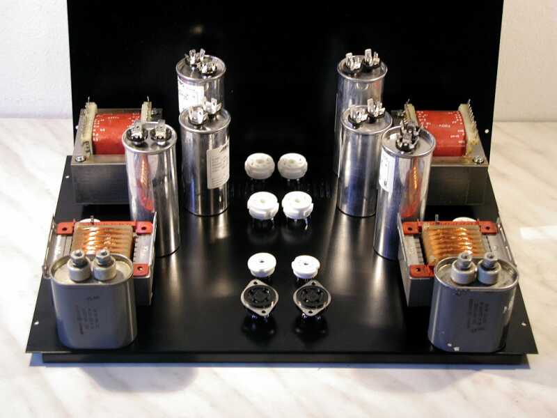
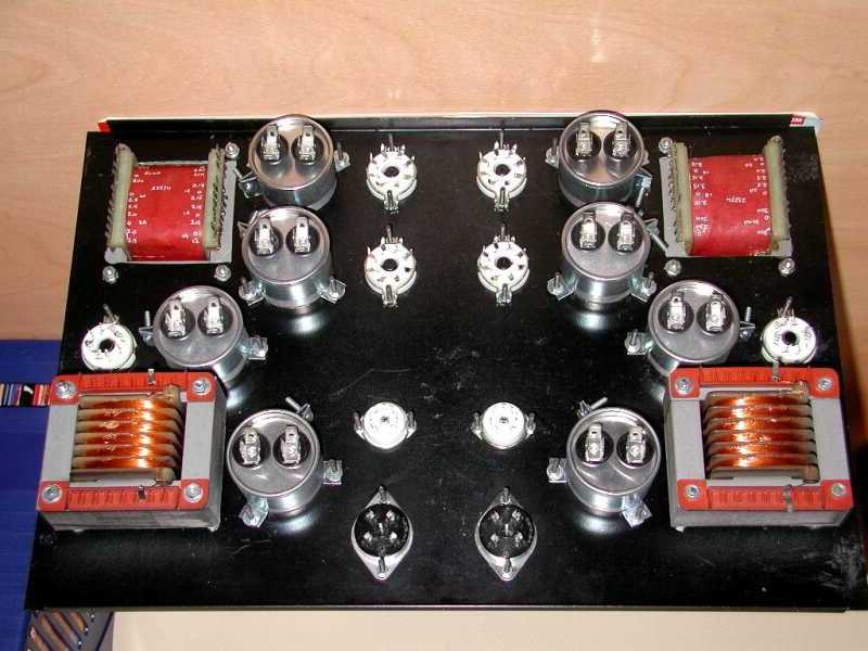
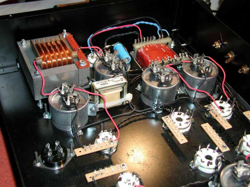
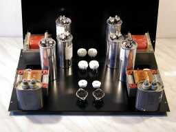
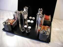
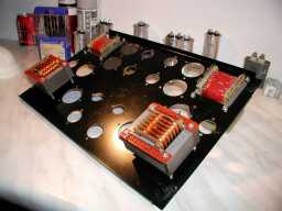
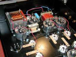
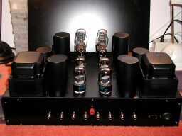
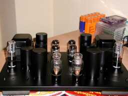 By mounting the tubesockets, we are now ready for wiring ! at the right
an impression how the topplate of the amp will look like with the tubes plugged in. No
need to mention, these will be removed before I start the wiring, don't I ???? At the left
picture you can see, that the lay out is very logical and follows the signal and Voltage
supply path for short non- interacting connections. As you can see, this time I took care
to make sure that the solderlips from the caps are in a logical order. I had forgotten
this at the KR300BXLS..... result, more messy wiring. So you see, I learn from my own
mistakes (every day again and again...) Next by the way is the drilling of the holes for
the frontpanel and the backplane. I will start wiring, when the whole chassis is
assembled.
By mounting the tubesockets, we are now ready for wiring ! at the right
an impression how the topplate of the amp will look like with the tubes plugged in. No
need to mention, these will be removed before I start the wiring, don't I ???? At the left
picture you can see, that the lay out is very logical and follows the signal and Voltage
supply path for short non- interacting connections. As you can see, this time I took care
to make sure that the solderlips from the caps are in a logical order. I had forgotten
this at the KR300BXLS..... result, more messy wiring. So you see, I learn from my own
mistakes (every day again and again...) Next by the way is the drilling of the holes for
the frontpanel and the backplane. I will start wiring, when the whole chassis is
assembled.
Update September 9th
I have prepared the back panel and front now and mounted the back. The amp finally
starts looking like an amp now !! I have let the front out so far, for easier access
to the connection points. In this way it is just easier soldering...
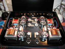
As said before. The more logical and symmetrical lay out
of this actually double mono amp, makes it possible to keep wiring short and very neat.
For all the signal wiring, I use the silver wire (0.8 mm) again. The isolation is
heatshrink tube. The AC-filaments of the 6SL7 and D3A can be done with simple copper wire
(twisted to reduce radiation of 50Hz Humm) This amp is a dream to build up. It really is a
great pleasure to have such a neat and clear lay out possible.... The use of the
SUB-grounding, makes the wiring also less complex and messy....
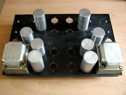
Here you can see the detail of one of the "mono" channels. Already taken into
account are the little connector strips for the resistors and capacitors. In the empty
area in the middle, the selector switch and Volume switch will be mounted
(later...)
This is how the back side looks like now. Even the cinch connectors are set up fully
symmetrical. I will use cinch-connectors with a 90 degree angle, so this is easier as all
interlinks will hang straight down....
Next will be the mounting of all the components !! I
hope to update this Site in another week from now.....
Update September 20th
This page became rather long, so continued at Item 1b
IMPORTANT:
The information provided on this page is intended as guide for DIY activities and
therefore free to copy and or publish. If any one wishes to use any of the information
from my WEB site, please make sure to refer and footnote to my URL Link as source! Doede
Douma