Updated:
13-Mai-06
DDDAC1543 MK2
Family Description & Construction
Introduction:
This page will describe the
construction of the 3 modules. I will not go in extreme details, but just "walk you
through" the basic elements of the DDDAC1543 MK2, so you can follow what I have been
doing.....
Again: I will not go into the basic details of the SPDIF Circuit principles and NOS DAC backgrounds, see therefore the normal dddac1543 section (click banner above...)
It might proof to be useful if you open the documents first, save or print them and have them at hand to keep an eye on the overall circuit.
------->> CLICK HERE for PDF high resolution Circuits (version 5.0) <<-------
CLICK HERE to see how to connect the modules of the DDDAC1543 MK2 Family
USB to I2S
Converter & DAC
Actually this a very simple
design and fully based on the PCM2707 datasheet of Texas instruments. Just like
that ? not completely, I "designed" a few extras to make it fit to my
requirements and the dddac1543.....
Of course this design can
be used fully stand alone or as USB to I2S converter for other (DAC) purposes. I
leave that to every ones discretion :-)
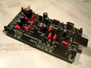
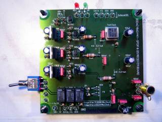
Thanks to the PCB construction is a piece of cake and the final result looks
like this:
Below is the basic circuit, which is almost self explaining. A few comments:
The power supply (not show again, see introduction page) is based on the same low noise power supply as on the other units
The output capacitors are quite large to allow headphone use
There is an option to wire for the Tent Clock or for the normal Crystal (I used a switch for A-B testing :-)
By closing or opening the "Select" switch you can choose between Analog output from the built in DAC or I2S signal output
So make sure to note !!! The PCM2707 will NOT output simultaneously Analog signals and I2S data output !!!!!!!!!

Click on the above
circuit for a high resolution version.....
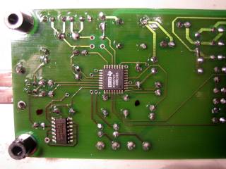
At the Left is shown, that the SMD components are already soldered at the bottom side of the PCB, making DIY life very easy :-)
SPDIF
to I2S Converter & Receiver:
From a technical principle,
the SPDIF receiver has not changed since the old DDDAC1543, but of course there
are some improvements !!
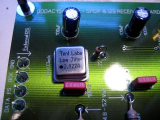
No option any more to switch between internal clocking and Tent XO re-clocking. I think the point has made in the meantime. The re-clocking does sound better, so make it a fix connection...
The use of the 2.8224Mhz Tent XO Clock, directly driving the I2S BUS (for comparison purpose, a 11.2896 MHz Clock can be used as well...)
As this PCB allowed for, I used for the FS clocking a higher speed SMD version of the 4040
Every chip has its own filtered decoupled power supply
Used resistors in the data lines to decouple chips from each other
The PCB is designed in such way, that connections to the DAC Modules and USB Receiver are just short bridges between the PCB's
A selection is possible to drive the I2S BUS from the SPDIF receiver or from an external I2S source (like the USB receiver for example !!!)
As the CS8412 is obsolete, I decide to use the CS8414 SMD version, which is apart from higher speed the same....
On board included battery checker. A simpler solution with "only" 2 colors, but as effective I think....
Enough words !!! How easy is it to build this receiver ???
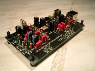
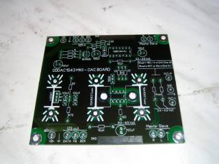
Very simple as you can see below: Just follow the pictures and the comments below. I think this describes it well enough !
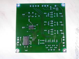
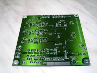
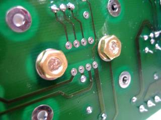
View of the bottom and top side of the PCB. Thanks to the component layout with values in stead of part reference (I hate this, you always need to find parts back from the circuit...) a not too difficult task.... For DIY convenience, the 2 SMD parts are already on the PCB
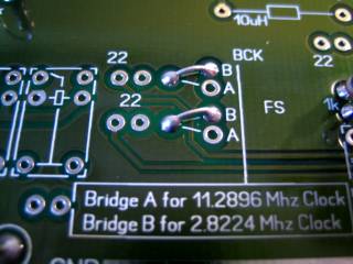
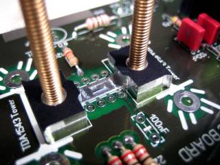
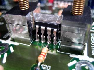
Left: Detail
of how to wire the bridges. In this case for the 2.8224 MHz Clock
....
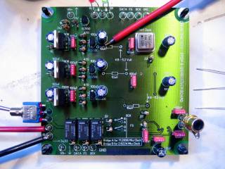
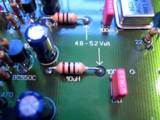
Right: Just to make sure !!!!! BEFORE soldering the 3x 10uH Coils (the
ones looking like resistors...) measure the voltage to be 100% sure and not
damage the chips (because than you can throw away the PCB !)
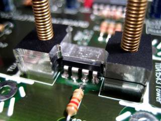
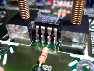
Just a few details on how to place certain components and how they look like, as this can be a bit tricky, saves you downtime and me a lot of questions, haha !
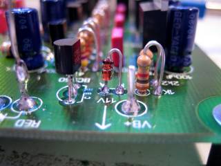
Note the placing of the Zener diode.... When the Vb drops below 11.4 Volt, the RED LED will light up. The battery is now approximately at 25% of its life
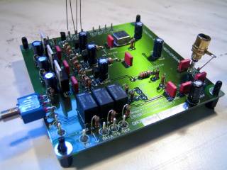
This is how it finally looks like ..........
Only one thing more to built, keep reading !!!!!!!
Master / Slave
DAC Module:
Looking at the number of
pictures, you might think that this is much more complex ? YES and NO is the
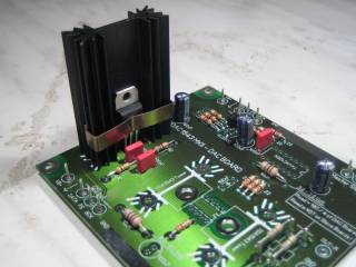
answer ! The soldering is easy thanks to the PCB. The most work actually is the
construction of the tower which will give an excellent
result for both mechanical stability as well heat sink wise....
The optional ( !! ) solution with the special tooling is not 100% necessary
of course. If you are a bit creative, it will probably proof to be doable to add
any heat conducting material between the TDA1543
chips and the heatsink. May be a aluminum
U-Profile or so ??? I leave this to every ones own ideas. I used the tooling as
the result is just very robust !
What is new ??????
As said, the major thing is the improved mechanical and PCB design, allowing a master slave combination
The inputs from the TDA1543 chips, (12 in total !!) is isolated from the I2S bus by buffers. This is needed to reduce the load of the SPDIF & USB receiver when going for larger numbers of DAC chips.....
Resistors in the data lines to decouple noise loops
I decided to remove the manual biasing and voltage adjustment. There is some spread now in the DC output, but this can be adjusted to linearly adjust the Rload afterwards if you really want. Never the les, by doing it this way, the design is more robust and less errors occur and everything stays well in range
The master slave combination need some explaining I guess.... If you use more than one board, the slave boards are not getting a Rload resistor, in stead the current loop is made through the PCB bridge connections to the master board and all currents come together in one Rload. From this Rload the Voltage (I/V conversion is done here...) is taken and therefore no issues with "longer" lines as it is all current source driven. Sounds may be somewhat strange to just connect all outputs, but in the tower nothing lese is done differently !!.
Not really new, but just as reminder --> The couple C and the bleeder resistors are NOT on the PCB, but soldered directly to the Cinch connectors. In the KIT I put 2x 100uF and 2x 100nF extra to be used in parallel as basic "starter" solution, but in fact you should replace this later with a real good couple C..... (see my story in the introduction site)
OK, here we go, lets built some :-)
Again, PCB design is very helpful identifying easily all parts. Start with all the small parts and do the tower for last...
Oh ..... not shown on a picture, but BEFORE soldering the 10uH coils, measure the supply voltage !!!! JUST TO BE 100% SURE !!!
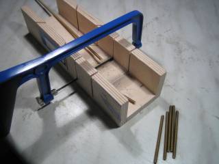
Now some
real mechanical work, hahaha !! Cut it yourself or use complete 70mm screws if
you can get them (I could not then, so needed to follow the hard way...)
NOTE: In the meantime I found them, so tooling does now INCLUDES 2pcs M4x60mm
screws... Life is easy, eh?
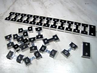
Than very carefully (don't push hard and twist the very thin aluminum
!!!) take the single elements apart
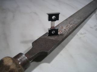
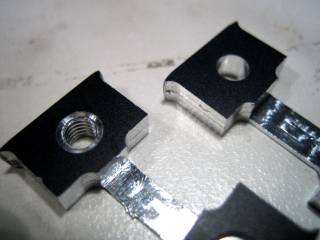
Make sure all sharp edges are gone. One piece has machine winding and is to be used as first tower element (M4 by the way)
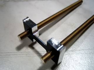
Now the basis is laid for the tower.....
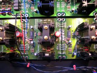
Tighten the screws at the bottom and now start adding chips and cooling elements.....
Clearly you see how the tower grows..... Work carefully to have the pins neatly lined up and avoid short contact with the tower (which is electrically mass)
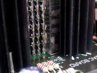
At the right
you can see that after the tower is fixed with the screws, all pins are
soldered to ensure good electrical contact from top to bottom.
IMPORTANT: before powering the module, take an OHM-(multi)Meter and check if the
pins at the bottom of the tower are truly connected
till the top of the tower. If needed, search for loose contact and solder again.
The same for cross contact (which should not happen of course :-)
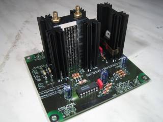
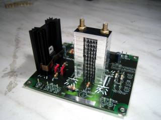
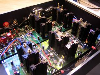
Finally the
tower gets its cap and as very last the 2 cooling elements are soldered next to
them. It all fits within the 1/10th of a mm, so no
real need for cooling paste....
The DAC Module is now ready and can be used also stand alone for example with a
PRO CD-transport with I2S output .....
The towers do still get hot, like 50 degrees or so, but NO FAN is needed.... nice and quiet, grinsssss....
The
DDDAC personal DAC at home :-))
Just to show
what you can do with the modular setup, I have built for my own private use a 60
DAC version !
Why 60 you might ask ???? Well, it just fits very nicely in a typical 43 cm chassis..... and to be a bit more scientific, I believe 60 DACs is roughly the maximum compromise between gain in sound quality and power consumption and cost ate the other side.... it will improve the linearity of the TDA1543 (which is actually quite bad) with 3 bits, which brings it to the theoretical 16 bits, so why do more ?
Never the less, as you can read in the results page 24 is better than 12 and 60 is better than 24..... but no dramatic difference, the "effect" is clearly converging.....
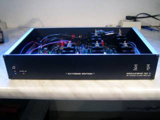
I think the
pictures tell the story........ What is absolutely clear is the easy way of connecting
all the modules :-))))
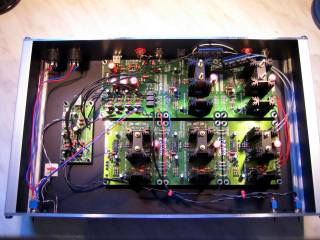
No need to mail me by the way, the USB receiver at
the left in the chassis is a prototype and therefore
there are longer wires to the rest of the DAC. In the final version this can be
connected just like the DAC modules ......
A few pictures more showing the inner life of the DDDAC1543 MK2
CLICK HERE to see how to connect the modules of the DDDAC1543 MK2 Family
added January 10th:
How to upgrade the "old" DDDAC1543mk1 with the USB receiver ?
Already got several questions from DDDAC1543mk1 owners, if and how they could update their existing DAC with the USB interface.....
Well, the answer is really simple !! just look below, I think the image tells more than a thousands words can do :-) Still the steps:
Cut the copper traces on the dddac1543pcb board, so that you can solder a wire to it at both sides if needed, so take a nice spot somewhere "in the middle"
Connect the BCK, FS and DATA lines to the copper traces closest to the side of the DAC chips of course
Connect VB+ and GND to the corresponding terminals at the DDDAC1543 PCB
Do not forget to close the 2 pins "select" with a piece of wire on the USB Board (this allows I2S signals out....)
Now it should work !!
Optionally, you could put a 3 pole switch with the middle positions towards the DAC tower and the 2 positions to the original signals/traces on the DDDAC1543 board and the I2S output fro the USB Receiver. With that you can select A-B if you listen to SPDIF or to USB .......
Above: how to connect the USB Receiver to the "old" DDDAC1543mk1
If you are interested to built a DDDAC 1543 MK2 system for your own, see my sales page and the KIT Story.....
Happy Listening and Building !!!!
Doede Douma
IMPORTANT: The information provided on this page is intended as guide for DIY activities and therefore free to copy and or publish. If any one wishes to use any of the information from my WEB site, please make sure to refer and footnote to my URL Link as source! Doede Douma