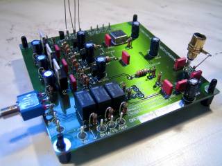
SPDIF to I2S Converter & Receiver Board

Qty
Updated:
23-Mrz-07
The
"DDDAC 1543 MK2 STARTER KIT Family"
lowering the threshold.....
Introduction
It turned out that the
DDDAC1543 starterkit was a great success. So many enthusiastic
DIY has built the DAC with great pleasure on the
construction and the listening results afterwards.... So Of course I have made STARTER
Kits available !! The
KIT had to contain all BASIC parts with very little exception, like chassis or
power supplies / Batteries and Tower Tooling. It should allow every one to built a working DAC with
GOOD results ! The GOOD NEWS is, that now every one can start tweaking the
DAC by selection afterwards, better R-load
resistors, better decoupling capacitors and
Decoupling caps..... or whatever you think is worthwhile
tweaking....... The components in the kit are
standard components, so exchanging some of them is
hardly capital loss ;-)
Tips for Tweaking the Kits
OK, OK, I understand, every one wants to improve immediately the DAC kits ......... So let me tell you what I think (so my opinion !!) you could do to improve:
1. Replace the output capacitors to BG (FX, N or NX), Auricap or even better Mundorf Silver/Oil or Gold/Silver. Or whatever high end capacitor of your choice.... This is the best possible tweak and should actually be done by every one building the DDDAC. Why is it not in the KIT then ??? Well, it is such a matter of personal taste, I rather leave this to every ones individual choice, taste and budget .... I am using the Gold/Silver ones
2. Replace (only !) the 100uF/100nF capacitor sets AFTER the inductors (10uH) with BG or similar Electrolyte caps of your choice. For example 100uF NX 6.3 Volt or use FX, or whatever you think is ok. I used the BG 100uF NX 6.3 Volt and for the one decoupling the TDA1543 Tower 1500uF BG Type N. Bigger seems better here !
3. A minor tweak --> Play around with the Rload resistors. I have heard (use them self as well) Riken are very nice...... But just experiment !! Is more fun too :-))
4. Bias Voltage tweaking.... I had several positive feedback (including my self) that when the Bias voltage (at pin 6 and 8) is between 3.8 and 3.9 results are optimal. It is not a BIG thing, but so easy to tweak..... For example, if you use a 24 dac version, make Rload 100 Ohm. On a 12 DAC you can try 200 Ohm. Always measure the voltage finally after half an hour when the tower is warm.....
What Kits do you
need to fit your need ?
Let
me give you a few examples what exciting options you can create by using the
modularity of the DDDAC 1543 mk2 :
| Configuration options | SPDIF receiver | USB Receiver | DAC Module | extra DAC Modules |
| Typical DAC for CD-Transport | 1 | 1 | 1 - 4 | |
| DAC-Upgrade for I2S CD-Transport | 1 | 1 - 4 | ||
| SPDIF upgrade for existing DAC with I2S input | 1 | |||
| USB upgrade for existing DAC with I2S input | 1 | |||
| Stand alone USB DAC with selectable output between PCM2707 DAC and TDA1543 in NOS | 1 | |||
| USB 1543 DAC | 1 | 1 | 1 - 4 | |
| The DDDAC personal DAC at home | 1 | 1 | 1 | 4 |
|
Check
the list with Pre Configured Kits First ! |
About the
DDDAC1543-KIT Family
So
what is you get ??? Check below the tables and you will see exactly
what you get. These parts are referring
to
the file DDDAC
1543 rev 5.0 and will allow you to built a working DAC
Update in March 2007: The new version of the USB to I2S converter and DAC 3.2 has fully replaced the "old" version and the list below refers to dddac-usb-1543-dac32
|
SPDIF to I2S Converter & Receiver Board
|
||
| Type | Part |
Qty |
| C1,2,3,10,11,12,16,17,18 | 100n | 9 |
| C4,5,6,7,8,9,13,14,15 | 100µ | 9 |
| Cinch connector | Black | 1 |
| IC1 | CS8414CS | 1 |
| IC2 | 74VHC4040M | 1 |
| IC3 | TENT XO Clock 2,8224 MHz | 1 |
| IC4,5,6 | UA7808 | 3 |
| L1,2,3 | 10uH | 3 |
| LED1 | GREEN | 1 |
| LED2 | RED | 1 |
| R1,2,3,5,6,7,8 | 22E | 7 |
| R4,10,20,21,22 | 1k | 5 |
| R9 | 2k2 | 1 |
| R11,12,13 | 10E | 3 |
| R14,16,18 | 470E | 3 |
| R15,17,19 | 1k2 | 3 |
| R Metal | 75E (solder at SPDIF input connector) | 1 |
| Relay 12V | Omron | 3 |
| Solder PIN | 18 x 1mm | 18 |
| Switch | switch 2 pole | 1 |
| T1,2,3,4 | BC550C | 4 |
| Z1 | 11V | 1 |
| PCB SMD Service | SMD Parts Pre Soldered | 1 |
| DAC
Board (Master or Slave)
|
||
| Type | Part |
Qty |
| C1,3,4,6,8,12 | 100µ | 6 |
| C2,5,7,9,19,11 | 100n | 6 |
| IC1 | TDA1543 | 12 |
| IC2 | 74VHC125N | 1 |
| IC3 | LM317T | 1 |
| L1,2 | 10uH | 2 |
| R1,2,3,4,5,6 | 22E | 6 |
| R7 | 120E | 1 |
| R8,9 | 180E | 2 |
| R10,11 | 100k | 2 |
| R12 | 82E | 1 |
| R13 | 470E | 1 |
| R14,15,16 | 1k | 3 |
| Solder PIN | 1mm | 15 |
| Cinch connector | Black | 1 |
| Cinch connector | Red | 1 |
| T1 | BC550C | 1 |
| PCB | 1 | |
| SK104 heatsink | 3 | |
| SK104Clip | 1 | |
|
USB I2S Converter & DAC Board with selectable output for PCM2707 DAC or TDA1543 NOS DAC (one chip) |
||
| Type | Part |
Qty |
| C1,5,8,9,11,12,13,14,16,18 | 100n | 9 |
| C2,4 | 33p Ceramic | 2 |
| C3,6,7,10,14,15,17,19 | 100u | 8 |
| IC1 | PCM2707PJT | 1 |
| IC3 | 74HC08D | 1 |
| IC4 | TDA1543N | 1 |
| IC5 | uA7806 | 1 |
| L1,2,3 | 10uH | 3 |
| LED | RED 3mm | 1 |
| R1,3,4,5,7,9,10,17,19,23 | 22E | 10 |
| R6 | 1M | 1 |
| R8,11,12 | 1k5 | 3 |
| R18,20 | 820E | 2 |
| R14,15 | 3k3 | 2 |
| R2,13 | 10k | 2 |
| R21,22 | 100k | 2 |
| R24 | 470E | 1 |
| R16,25,26 | 1k | 2 |
| Relais | Finder 30.22.9.12V S | 1 |
| Solder PIN | 1mm | 12 |
| Switch | switch 2 pole | 1 |
| T1 | BC550C | 1 |
| USB-B | USB B Connector | 1 |
| X1 | 12Mhz X-Tal | 1 |
| PCB SMD Service | SMD Parts are PreSoldered ! | 1 |
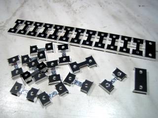
TDA1543 tower
tooling
Precision
tooled aluminum. Also see construction site. See picture below on top is what
you get, below how it looks after you twisted off all the single parts.....
Note: The Tooling INCLUDES 2pcs M4x60mm screws and 2 M4 nuts to mount the tower on the PCB !!

Happy Listening and Building !!!!
Doede Douma
IMPORTANT: The information provided on this page is intended as guide for DIY activities and therefore free to copy and or publish. If any one wishes to use any of the information from my WEB site, please make sure to refer and footnote to my URL Link as source! Doede Douma