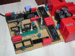
The PCB with the Receiver, Digital Filter and DAC Stage. Clearly to see are the switches for making combinations.
Updated:
24-Jan-01
One of two possible options to build the receiving and filtering circuit
It is recommended to download first the PDF Document DDDAC1.pdf with the schematics.
For pictures of all the parts please see the Technical Backgrounds Section and Picture Galery

The PCB with the Receiver, Digital
Filter and DAC Stage. Clearly to see are the switches for making combinations.
In the DDDAC1.PDF document I describe 2 digital filter sections. Of course, thanks to the switches, any combination can be made here, but to keep it simple I describe 2 "combinations" from which this is the first part:
Receiving Part:
Clearly painted are the two optical TOS-LINK receivers (347kB download)and the coax cinch input with pulse transformer. This data is AC coupled linked to the input of the receiver CS8412 (643kB download). The 8412 is a well know simple straight forward receiver in Hardware mode. Internally, the system clock is regenerated with a phase locked loop (PLL). This ensures an almost jitterfree clock for the digital filter and DAC chip, thus minimizing the effect of the data-transmission link (I even use a 10m optical fiber cable without any problems!!).
The chip now further decrypt the 16 bit CD code into the 4 basic audio signals which are industry standard:
| Data | This is left and right data in Left/Right sequence, where each "word" uses 32 bits length, even though the data is 16 bit long. This is done to keep the standard open for 20, 24 bits and ...... The Data is in RIGHT JUSTIFIED MSB first. There are more modes in the digital data world, but this one is the most commonly used for Audio equipment. |
| Fs | Fs is the actual sample frequency, for CD this is the well known 44.100 kHz |
| Bitclock | The bit clock, clocks the bits into the digital filter at a rate of 64 x Fs (2 words of 32 bits), thus 2.8224 MHz |
| System clock | The final system clock runs at 256 x Fs, enabling the Digital filter to output 32 bit words Left and Right in parallel at 8 times oversampling (32 bits word x 8 times oversampling needs 256 Fs), Page 3 of the DDDAC1.PDF describes this overview as well. 256FS comes to 11.2896 MHz |
and are fed into the .........
The Digital Filter
The digital filter is doing many things with the original signal, like calculating interpolating "new" samples. The oversampling runs at 8 times, Therefore the Filtering of the sample frequency components after the DAC later on can be much simpler. In stead of a BRICKWALL filter you can use simple 6dB linear filters. The digital filter also filters in the digital domain already all frequencies above the audioband as with the interpolation all kinds of "new" frequency products see the light. It may be clear that the quality of the filtering algorithms and speed of the digital filter is critical for the final result. The NPC chip SM5842 is a top of the range filter with studio quality. For those wanting more details, have a look at the datasheet of the SM5842AP.... (201kB download). The 5842 need to be set up for the right number of bits at the input (16 or 24 bits) and output bits (20 for the PCM63). This is done with the switchbank. Of course you can choose fix connections to V+ or GND (as proposed in the version 2.0). Furthermore there is an option to chose jitter free clocking and Low level signal dithering. To be honest, I could not really tell the difference when listening to it.... But may be you can.
The digital filter outputs its newly generated data with the industry standard 4 signals:
| DOL | Data Output Left | This is left channel data where each "word" uses 32 bits length with 20 information. The Data is in RIGHT JUSTIFIED MSB first. |
| DOR | Data Output Right | This is right channel data where each "word" uses 32 bits length with 20 information. The Data is in RIGHT JUSTIFIED MSB first. |
| WCK | Word Clock or Latch Enable |
The word clock, starts the conversion after all bits have been clocked in serially. This speed is 8 x 44.1 kHz equals 352.8 kHz |
| BCK | Bit Clock or System Clock |
The final system clock runs at 256 x Fs, controlling the serial clocking into the DAC of the 2 channels in parallel (!). |
These 4 signals goes to the final DAC chip stage for the Digital to analog conversion. Basically you see that the whole setup of a DAC is more of less modular with standard interfacing signals. This makes experimenting and upgrading much easier.
IMPORTANT: The information provided on this page is intended as guide for DIY activities and therefore free to copy and or publish. If any one wishes to use any of the information from my WEB site, please make sure to refer and footnote to my URL Link as source! Doede Douma