Updated:
13-Dez-04
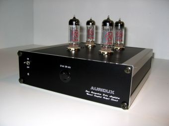
AURIDUX
An Directly Coupled,
Electrostatic Headphone Tube Amplifier...
For the Stax SR404...
Introduction
And now for something completely different ....... A headphone amplifier ...... and one which is pretty unconventional I must say. Why? I just wanted to do something completely different in my Audio system. I used to own a Stax Headphone (type M-5 or something like that) many years ago and although it was clear this was a very basic unit, I was very pleased by the very transparent sound. Working on the Gydinel project and spending an outrageous amount of money on the Thiel D-20 diamond tweeters I also was plagued by the "question" how good these tweeters actually in absolute reference are?? All the stories about reference electrostatic headphones came to mind and I decided to just give it a try and I bought a SR-404 Stax Headphone. Not the absolute top model, but quite close ;-) I also wanted to use this as a reference sound source to judge my loudspeakers and on top it would give an other option to enjoy high end music.....
Buying the unit was not the problem, through Ebay, I found one 40% ( !! ) below normal list price and brand new also. The real challenge for me was to build an amplifier which could easily drive this unit and was really adapted to the fact that it is a capacitive load. Now the quest really started..... many ideas in the internet, but MOST of them were based on tricks how to use a standard amplifier and connect the unit in one way or the other to it. For me it was clear an output transformer should NOT be used... With Tubes you can directly build a high voltage amplifier and connect the unit directly, so why bother? Never the less, not so easy as it might look. A single ended design cannot be done, as you need to drive the unit in balance (the rear and back stator to be precise). A regular balanced amplifier consumes a lot of power as you need to give some load to the output.... Next thing which came to mind was to use a differential amplifier. This would have a lot of advantages: Power supply will be completely outside the signal path, so could be relatively simple. If DC bias is done right, no coupling capacitors are needed and no need to PRE-Load the amplifier. So relatively small signal tubes can be used. My eye dropped on the ECC99... a very nice tube, good sound and capable of working under relatively high voltage.
Sound simple eh? Unfortunately it is not.... This ended up to be not a beginner project.... Let me try to walk you through the design basics and evolution below. Just download the circuits for reference.....
This is the original specification of the SR404 Signature and here you can download the AURIDUX Circuits version 2.2
Design Description
and Evolution
Below I will try to get you into the basics of electrostatic headphones and how to drive them......
Above circuit is the basic principle of (any) electrostatic speaker. A unit is constructed where 2 isolated metal panels, the stators, are being fed with a balanced signal. In the middle there is a diaphragm which is charged at a high voltage (headphones are like 10% of real large loudspeakers as diaphragm movement is minimal) so when the voltage balance between the 2 stators starts to change (also called music :-) the diaphragm will start moving and reproduce music. As the diaphragm is very light and there is no enclosure, it is very fast, transparent and absolutely neutral.
The standard way to drive an electrostatic speaker is to use an output transformer (or input?) and transform the LF signal from your normal power amplifier UP with a factor 10 to 100 depending of the type of speaker. As this is done with a transformer it is very easy to balance the signal output which was needed to drive the stators... Headphones normally will do with a factors 10 to 20....
In the Internet you will find many many Sites specially dedicated to electrostatic loudspeakers, so I will rest my case at this point .....
The other alternative way to drive an electrostatic headphone is to take your Push Pull tube amplifier (when you have one...) and tap the signal at the primary side of the output transformer... The voltage swing here will be more then enough to drive the headphone to the max.... Even the Bias could be taken from the Ub from the amplifier. Very very simple, but we should not forget, that this system is NOT so linear. The Output of the Tube amplifier will be totally depended on the (transformer) load..... In fact and that is clear, the headphone runs in parallel.... Also you cannot use the loudspeaker as you need to drive the amp at full power.... resistors at the output will also be quite warm..... again, very simple and very effective, but not what I had in mind :-)
We make a small jump now and come directly to the basic principle of the Auridux.... This not how it is built by the way, just basics !! but that will be discussed later. For now the principle.... This circuit is nothing else then a standard differential amplifier. One input is grounded, so we can drive single ended signal in... The balanced signal between the anodes of the 2 tubes is now directly fed to the headphone.... Directly coupled !! No Capacitor, No output transformer..... very promising..... This can actually be built just like it drawn above... BUT I wanted to take it a step further.... 2 points I did not like on this setup
1. The load resistors Ra will consume a lot of power and introduce non-linearity. No hard thinking here. So far I have been using the concept of Mu followers very successful and the results have always been audible good and specification wise the best. So I decide to make a Mu follower with the ECC99... This is clearly visible in the original circuits
2. To make a nice linear differential amplifier which is truly DIFFERENTIAL, the value of Rk must be very high to limits its influence on the 2 sections above. This would result in unpractical negative supply voltage, making things unnecessary expensive. Rk will be not in the signal path when it become large enough, So my logic thinking was to put a current source at this spot.... To make things not overly complicated I used a MOSFET current source. The same MOSFET I used in the TUMOS amplifiers. Now it is sufficient to have a relatively low negative supply voltage and thanks to the MOSFET the current source represents almost an infinite value for Rk .....
Circuit Description
Normally I don't like do this so much as most Tube circuits are quite standard and familiar, but on a first glance the circuit might look complex. In a way it is, but let me take you through (best to print it out and follow the text)
The amplifier (Page 1)
Signal comes in at one half of Tube 2. To allow for single ended input signal, the other half is grounded. Tube 1 is used to form the Mu follower sections. Signals go through C1 and C4, so Auricap or an other good capacitor is desired.... P1 and P3 are kind of new in this position. Theoretically they are not necessary, but the 2 Mu followers will auto bias at different levels due to small differences in the specifications. Also over time the bias will change... Why 2 trimmers? well actually you can trim now the output DC-voltage per stage at an absolute level, so the bias is exactly "in the middle" allowing for maximum output swing (we NEED that of course !!) and by having 2, we can also minimize the DC delta between the two outputs, so there is less DC pre load to the headphone. It came out in practice that this is absolutely uncritical and you hear no difference at all when DC delta is even like 10 or 20 Volt. But it feels better to trim to a minimum. A few volts is surely doable...
Even though the power supply is for 99% out of (signal) sight, I used the very nice Black Gate WKZ capacitor to finally filter the DC signal coming in.... The wires going to MP 1 to MP3 are just Measuring Points. We will come back to this....
Lets go to the bottom now. Here we see the Current source built up around the 2SK1058. The most right TL431 is the reference 2.5 Volt, used to set the correct cathode current. P2 is used to trim this to the desired value of 30mA (15mA per stage) R11 is a combination of two 1% 10 Ohm resistors in parallel, only used to be able to measure the Bias current with a multi-meter in the 200mV range .... The left TL431 delivers a very clean DC to the MOSFET, minimizing any rest influence of the preceding DC power supply and keep signal paths short
One last commend.... the amplifier has a gain of MU/2, which equals approximately 10x This means you need to drive it from a tube amplifier which van do 20 Volt output.... Otherwise you cannot go to the limit of the headphone (which is rather loud I may say..) (For fun, I have tried it directly to the output of the Sony 777 SACD..... very small signal path :-) sounds great !
The Bias adjustment & measuring (Page 2)
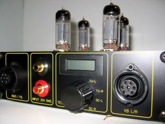
Already mentioned, this is NOT a plug and play tube amplifier. You really need to adjust at many points !! Also this should be checked and readjusted once in a while as the tubes age... Putting the amp upside down, open it and start putting multi-meter cables inside (may be causing short circuits, ahem...) is not a very appealing proposition, isn't it? The solution I came up with, is to put a fixed Multimeter in the amplifier itself. Actually very simple. You can buy small LCD panel units which work an a 9 Volt DC battery. As they are used in normal Digital Multi Meters....
With the selector switch, you actually select WHAT you want to measure and by clever wiring and making use of a reference voltage, the ONLY thing you need to do, is to trim and adjust he reading as close as possible to ZERO.............. easy eh? This will allow for regular adjustment I guess.... For that reason, I have made the trimmers accessible through little holes in the top plate, so no need to open the chassis.
The High Voltage Power supply (Page 3)
To make things not totally over the top or over complicated (and expensive, grinssss ;-) I have chosen for an active rectifying with soft recovery diodes BYW96E... We should NOT forget that this is NOT a single ended tube design, but a TRUE differential approach.... The power supply is highly outside the signal path..... Still I go for sure and use 2 big 100uF JJ Electrolytes and a 10H choke to make the rough (rough?? ;-) Supply DC. Remember, in the amplifier Chassis itself there is another section with the Black Gate !! Any way, I wanted to make sure the Power supply is QUIET as dead !!! With headphones, the smallest Humm will be devastating so close to the ear!!
The negative supply rail is done simply with a 3 leg regulator at minus 24 Volt DC..... This one is the furthest away from the signal path, so not critical...
The power supply is a separate chassis as I wanted to minimize the influence of the transformers on the tubes and is switched on through a switch on the front of the amplifier chassis. Therefore it is possible to put the power supply chassis somewhere unattended behind the audio rack :-). This caused me one problem... I did not wanted to have 220 VAC line running through the power supply cables. I just wanted to have a no-current solution here. The solution is very simple as you can see at the bottom of this page. I use a separate small transformer (so the idle current for stand by is also very low...) and a simple DC regulation with D5 and C1 to switch a relays which again switches the main transformer. The real TRICK now is, that in idle mode the relays is activated ! This means that to switch ON the amplifier, I break the contact and the relays will fall off. So now NO current is flowing when the amplifier is switched on.... No big deal may be, but why not?
Last detail are the relay contacts called "relay delay" (nice rime, eh?) read on ---------->
The High Voltage Power supply DELAY (Page 5)
This was actually installed later.... The problem was, that the high voltage was immediate on the tubes before the filaments were on their 100% glow temperature. This lead to terrible HUMM for approx 20 seconds. Not bearable !! A solution was needed !! Well, this is so standard, you can use it for ANY tube amplifier. Actually your tubes will love you, as they will be able to get on glow before you put the high voltage on it..... With the LM 311 here a small 30 seconds timer is constructed and it works just perfect..... Switch the amplifier on, the tubes starts glowing and after 30 seconds out of nothing suddenly MUSIC !! yammie :-)
R5 and R6 are to reduce the inrush current, later more at the measurement section....
The Bias and Filament supply...
The bias for the Stax is set by the factory to be optimal at 580 Volts DC. This is not an easy voltage to achieve with little effort. And actually that is what I wanted.... My luck was, that the supply is only to charge the diaphragm of the headphone, so its output impedance is made deliberately very high > 10 MOhm or so. This is very helpful, as one diode bridge and a few small capacitors will do....One little problem was the adjustment..... As in quantum mechanics, the measurement changed the result :-) Or more down to earth, the voltmeters impedance is too low !! So I made the helping circuit of R6 and R7. Use a scale of 2 Volt and adjust to 1.56 Volt, so max resolution... works prefect !
On the bottom side of the page, you can see the standard PCB's with the LM317 for the filaments which are of course are supplied with a clean DC voltage !!
Project
Description
Let me take you by the hand of some pictures through the construction of the Auridux ---->
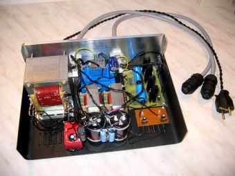
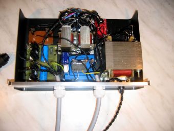
The Power supply Chassis houses the main transformers, rectification, choke and "rough" DC supplies. Nothing special, just a standard metal case from Conrad Electronics.....
This is a
different story :-) Again I used Sch�fer to have a perfect looking chassis
produced which fits exactly in the line with the DDDAC1543 and the PhonoDude
....
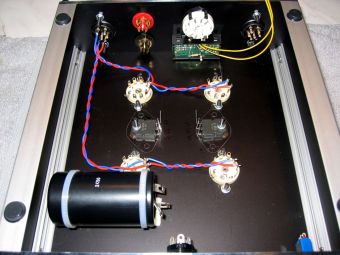
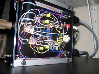
Building up starts with the filament wires and the MOSFET current sources.
Cooling is done by mounting them to the top plate. This proved to be more than
sufficient. Then all signal wires are soldered. I always use pure silver wire
0.8mm fitted in 1mm Teflon tube...
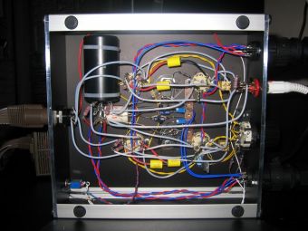
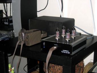
The finally wired chassis at the left and the whole set up with headphone at work at the right.... The connector at the front is a special Stax model and I had to buy it from a dealer in the USA... not so easy and ridiculously expensive for just a connector... but what can you do without cutting of the original plug from the Stax ??
Measurements
No design is published here without measurements (I start repeating my self :-) So below for those who have some technical interest...... enjoy the magnificent specifications !! I was really very much pleased by it my self...... tapping my own shoulder is allowed eh?)
Standard plot fro the frequency range. The headphone is connected !! Low cut off -3dB at 1 Hz is sufficient enough.... The little dip round 1kHz looks bad, but do not forget this is a 1dB/div scale ! The curve is straight within +/- 0.2 dB
Now the upper part of the curve.... -3dB High cut off at almost 600kHz... wow....
Distortion at 75 Volt RMS output (my ears are hurting !!) only 0.3 % from the very pleasant d2 sort. d3 is further 10dB down...
This is to get an impression of the symmetry of the differential amplifier... The 2 sine wave signals only differ 2%. This is high class for tubes !!! With a real resistor you will get to values of 10% to 20% ..........
The same, but another representation. This signal is de delta signal... The shape of the delta is also very smooth, no hick ups, no strange things
Headphones requires a very quiet amplifier of course, so I measured the noise spectrum at the output. Versus full signal (that is how you measure correctly and meaning full the signal to noise distance) the average noise is -125dB and the 50Hz noise component "peeks" at -100dB. Absolutely TOP !!
This was only to prove my self that the negative rail, which is done with solid state components, was absolutely noise free. -90dB versus 1 Volt and that behind a high impedance current source :-)
This is to give an impression from the Mu stage operation. We measure at an output of 38 Volt effective. If we would use a Triode loaded with a normal Ra (as standard tube amplifier designs do), we would measure of course 38 Volt. Now we measure only 1.4 Volt. This means that the real load for the triode is 27x Ra (R7 and R15 by the way) equals approximately 100kOhm. The ECC99 loves me for this and rewards me with, as we already could tell from the above, extreme linear functioning :-) Logically if you realize that the current swing is only 0,36mA at a bias of 15mA .....
This was the reason to use the delay... The first 20 seconds the high voltage is 525 Volt (scale is 150 V/Div) and drops when the tubes are warmed up.... So go for sure, I take a 30 seconds delay before the high voltage is switched on...
In the first test version, I blew out the rectifiers a few times... The rush in current was just too high when the High voltage kicked in, so I soften things down with the impedance value of a Tube rectifier..... Things are much smother now......
Agree that these are dream specs for a tube amplifier actually connected to the loudspeaker ???
Listening
Of course I had high expectations based on the measurements and the fact
this is one of the few best in class headphones you can lay your hands on. And
indeed every thing fall in its place when I started listening to the Stax
on the Auridux... The sound is so extremely transparent,
hard to believe without hearing your self.... What was even better was the 100%
neutral sound of voices and instruments. As there is no enclosure, there is no
coloration of sound what so ever !! And than the bass....... goes straight
below 20 Hertz. You FEEL the pressure
on your ears !! Really sensational.... Any
thing negative? Yes, unfortunately, the headphone
is not able to build up a 3-d sound stage as good as a normal pair of
loudspeakers can do. Never the less the sound is extremely spatial, so when you close
your eyes, you still feel like being there.....
Conclusions !!
It was actually a great pleasure to come up with something complete
different.... The results were completely as I hoped and anticipated, so my
audiophile listening corner has now a very interesting alternative to use :-)
And what about the comparison with the Gydinels ? In terms of tonal balance and neutrality the Stax wins, but the Thiel units are so close, I feel no need to start building something else.....
Happy building, listening AND testing.......
Doede
IMPORTANT: The information provided on this page is intended as guide for DIY activities and therefore free to copy and or publish. If any one wishes to use any of the information from my WEB site, please make sure to refer and footnote to my URL Link as source! Doede Douma