Updated:
04-Jan-06
Doede's Tube Stories...
New Project: A
complete new 300B single ended Mono Block AMP
Inspired by the work of
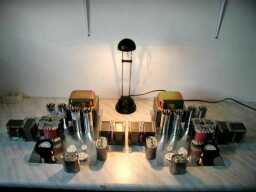
Triode dick’s BIG-C, I decided to build a similar AMP. Reason? My existing 300B amps
are very nice, but are kind of small, are difficult to upgrade and use quite standard
transformers. So I decided to build a second set with the best materials I could get.
Specially wound transformers by Wil Blauw, OPT with Amorphe Core and some more power
reserve, by using the KR300BXLS. For the last one, there was an extra reason. Welborne Labs, a USA dealer has
these tubes on offer for 325 US$ PER PAIR !!! The dealer in the Netherlands for example,
named "Eurogram" is
offering this Tube for 2.700 Guilders per Pair !! So this opened the door to use this
great tube…. Ofcourse I checked with the Dutch dealer if there was a mistake, but no,
they just wanted to earn some more money I guess. Only some fuzzy words on VAT, shipping
cost and supposedly old technology (?) But what I ordered is exactly the same, so who
cares, If you want some, hurry up, they were ON SALE !!
The schematics, you can find at the download area ….
The design basics are:
- MU stage with own power supply and driver Tube 227 or 56, Penthode D3A (secret tip)
- KR300BXLS tube with Amorphe Transformer from Wil Blauw (see Link Site)
- KR300B running at 400 Volt @ 140mA resulting in aprox 15 Watt Class A Output
- GZ37 and AZxx rectifiers
- Angela Oil C’s and open space for different rectifiers
- Combination of Hovland and PIO signal coupling C’s
All parts are ordered, so I only need to build it…… and you will be able to
read about it:
(update August 21st)
The final version I just built combination consists of:
- MU stage with own power supply and driver Tube 227, Penthode D3A (secret tip)
- KR300BXLS tube with Amorphe Transformer from Wil Blauw (see Link Site)
- KR300B running at 400 Volt @ 140mA resulting in aprox 15 Watt Class A Output
- GZ37 and AZ11 rectifiers
- ACS MKP in Oil C’s
- Combination of 2 types of PIO signal coupling C’s; Plesley and Sangamo
Description of the
circuitry:
The best is to download the ver2.0 of the
schematics first. If we follow the circuit from input to the output, we first see a
simple circuit, feeding the sub-woofer output at an f0 of aprox 100Hz. Whatever any one
can tell me on the great bass performance of Single Ended designs, the Bass is not the
kind of bass you would like to have and feel. Fat subwoofers will not lett themself drive
by 10 Watt or so, therefore the optimum solution is a hybride system like I am using.
Sometimes I switch them of, just to check, but the whole soundstage is suffering, loosing
athority and also sound stage (!). OK, enough I am dwaling..... the next stage is
the unbeaten MU stage. Read the other articles on the MU stage for
more info. Basically, the MU let the triode work at constant current, thus letting the
triode swing complete freely!!! this make the sound extremely open en clear. The penthode
source follower delivers current and a very low output impedance to the driver stage.  The miller C in the B300 will love you for that. no slew rate, nothing! (this
amp goes as far as 170kHz at 3Ohm with 15Watt !!!) This time I choose for the early
day version of the 27; the RCA 227. A beauty under the old triodes; very smooth and open
in a MU stage. De MU stage current source is the D3A; high transconductance and giving
more body to the sound than the 6688. But both will do perfect!!! Not unimportant:
the 6688 is much better to get than the D3A. With the Anode voltage at 150 Volt, the
output of the MU stage will be aproximately 60 Volt effective with still low distortion.
This is a bit on the edge, so I will experiment later with a different working point. I
gues 170 Volt will be fine. the 150 Volt is not bad or so, but the 20Volt could deliver
the extra headroom, for when it really goes loud ! The grid resitors were stock on hand
and are not critical. I tried to use Riken and Carbon as much as possible in the critical
spots.
The end stage is very basic and carries no secrets. Only one little trick:
a switch in the amp, let you make a choice between High current and Low current. With
1kOhm Rk you can use almost any B300. I tried the AVVT300B's and they work fine at 85mA
(hot hot hot). In the turbo mode, 140-145mA with Rk of 520-540 Ohm. The Output Transformer
is a specially wound amorphe version for this tube. And not without result! The amp goes
as low as 28Hz at full 15 Watt power. Actually the amp can go further in peaks going in
grid current. The MU stage keeps on delivering! no unpleasant distortion or so. The amp
sound therefore bigger than that it already is......... The Paper In Oil capacitors are
connected close to the OPT and MU stage, for decoupling.
The coupling internally in the MU stage and between the stages is very
sound affecting. Also a nice playing field for tweaking around with C's. There is no real
truth here, just try and follow what you like. I started with 2 different types of paper
in oil types. But I will try also the Hovland MUSICAP's. As said playing field is open !!!
The power supply is separated, to give the driverstage a Ub+ like a rock!
It also gives the opportunity to tune the voltages to what you actually need. The
KR300BXLS is a real bodybuilder and needs more juice..... Also the best rectifier for the
job can be chosen. A GZ37 for the power stage and the AZ11 for the Driver. Don't worry
about the resistors in series with the GZ37. There was made a little mistake with the
transformer for the filaments.... I found out when every thing was built in, hehehe... So
instead of 5 volt, I had a 6.3 Volt winding. I will later change this to the AZ11, so I do
not draw too much current from the 6.3 Volt winding. I used the ACS MKP in Oil Capacitors.
I already had some experience with these new current production components. The sound is
very close to the old (harder to get) old paper in oil C's. May be a little bit less body
/ fat in the midrange (just a little). I can hear (and measure) a very little 100Hz
component in the speakers (put my ear in it, hahaha) I will check later and see if a tweak
is necessary. (this tweak will be a snubber C over the Choke with fo=100Hz)
A few last words on the grounding of the Amplifier. I am using a version
of the central start earth. All ground connections than flow to one central point close to
the first filter capacitor. It can be done even better and this to use sub grounding. All
grounds round a stage are connected together close to the tubes and the components and
from this point one wire will go to the central point. Result: also a quiet amp and
shorter signal connections round the tube, leading to somewhat more transparent sound.
Description
of the construction:
This time I
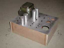
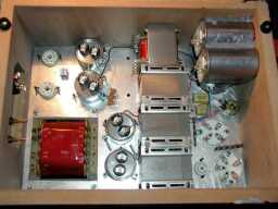
spent relatively long time on the mechanic side of things. The 2 pictures
below shows the arranging of all the components. This was not easy. I wanted to keep the
amp relatively small (30x40 cm) so I needed to use both sides of the top panel....
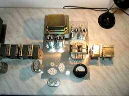
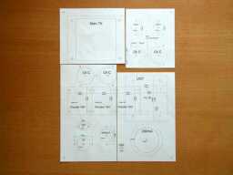
To make sure, everything really would fit, I took the time to draw a
complete stencil on 1:1 scale. This was later attached with tesafilm to the aluminum plate
and drilled through with a 3mm drill. The reference was set now with high precision and NO
MISTAKES !!
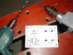
The sockel is made of MDF board. No screwing, just gluing !!!!! The
Mainstransformers are heavy enough to keep the pressure on the sockel.... Now it is time
to do final checking, last sanding and making the holes look best!
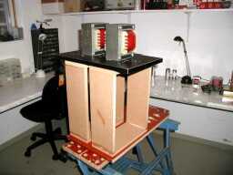
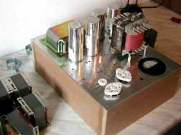
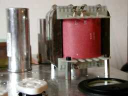
Now the assembly phase. The amp is growing rapidly now
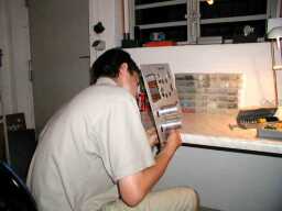
In the inside there is room enough now to make the wiring. I use 0,8mm
silver wire except for the indirect heated filaments and the mains connections. No cable
tree's, no bundling, just open loose wiring, keeping distance between the wires and
leading the filaments (twisted !!) close among the chassis
Actually, before the wiring, I sprayed the amp in a matching color with
my speakers. I just used spray can's from the Home Construction Store. Do not forget to
use a nice primer first! This will let the final paint stick much better

Only a case is needed for the OPT...... final detail (as usual, eh?)
to be cont’d with
further tweaks etc
See
Audio tweak #09 to see 2005 update
IMPORTANT:
The information provided on this page is intended as guide for DIY activities and
therefore free to copy and or publish. If any one wishes to use any of the information
from my WEB site, please make sure to refer and footnote to my URL Link as source! Doede
Douma
 The miller C in the B300 will love you for that. no slew rate, nothing! (this
amp goes as far as 170kHz at 3Ohm with 15Watt !!!) This time I choose for the early
day version of the 27; the RCA 227. A beauty under the old triodes; very smooth and open
in a MU stage. De MU stage current source is the D3A; high transconductance and giving
more body to the sound than the 6688. But both will do perfect!!! Not unimportant:
the 6688 is much better to get than the D3A. With the Anode voltage at 150 Volt, the
output of the MU stage will be aproximately 60 Volt effective with still low distortion.
This is a bit on the edge, so I will experiment later with a different working point. I
gues 170 Volt will be fine. the 150 Volt is not bad or so, but the 20Volt could deliver
the extra headroom, for when it really goes loud ! The grid resitors were stock on hand
and are not critical. I tried to use Riken and Carbon as much as possible in the critical
spots.


