Updated:
11-Jan-03
TUMOS, the MOSFET power amp module with real Tube
sound
In the download section, a full pdf document can be downloaded......
Genesis of the
TUMOS:
This started after a lot of discussions
with my audio friends on how to build a 3 way system with supporting Subwoofer, so 3
1/2 ?? After the great experience with the DD Master SUB and some
other set ups with Gydo and Jan, I am absolutely convinced, that every system is improved
by adding a normal closed speaker system with a Subwoofer module where the lowest
Octave Roll Off can be compensated(like the SW2.0 from Thommessen), leading to power full
bass foundation from as low as 20 - 30 Hz. But I am dwelling a bit... The discussion is on
a 3 way system where the first cut off is round 250-300Hz. Normally this leads to
very large Capacitor's and Coils. Not to mention that filter design is complex in
this area any way; the speaker impedance is far from constant due to the impedance peak
round the systems resonance frequency. The pro was that the sound would be homogeneous,
the pro for an active solution is the direct drive of the low speaker plus the fact, that
the SE amp (what else would you use for the mid/highs, hahaha !!) could be filtered at 200
Hz, leading to much higher output as the low frequencies normally use the most power from
the amp, less distortion etc etc.... But what to use to drive the low amp?? An other Tube
amp ?? PFFFF, very expensive and the bass reproduction is not the best in this world. A
Subwoofer module ?? may be.... but these have normally lot's of OPAMPS, and
lots of negative feedback, probably not leading to a nice co-operation
between the lows and midds, which I prefer to do 6dB any way... So I decided
to built a hybrid amplifier, Tubes for Voltage Gain, MOSFET's for power
amplification, no NFB of course.... Than I realized that the Voltage gain is already done
in the SE amp's driver stage, so why not use this signal and only give it a simple 6dB
filter (one RC at the input) and design a simple 1x power amplifier ??
So the following Whish List was defined:
# Voltage Gain 1x
(The tube driver will do the voltage gain)
# No feedback resulting in tube amp like output impedance (0.5 - 1
Ohm) to sustain sound character with the SE amp
# Clean and stable power supply
# Modular setup, so the amplifier can be used in many other applications
# Minimum of 10 Watt in Class A at 6 Ohm (average impedance of the
C220) and peak power of aprox 30 Watt
I will spare you the process of several design stages and component selections, but below you will find the basic result:
TUMOS Project Description:
Basic description:
Below is the circuit of the TUMOS
Most of the circuitry is to give the end stage the right BIAS. Basically this is done to give the gates of the MOSFET's a positive bias voltage of aprox 2.3 Volt each (for 1 A, which you need for 12 Watt class A in 6 Ohm) The 2 Voltage regulators are providing a basic voltage level to feed the TL431, a super shunt regulator with very good name in the audioworld. The P4 trimmer is only used to center the signal round ground. Through a few resistors (do not want load the driver stage with the TL431, the FET's get their bias. The OPAMP is used as an integrator and is only active below 20mHz or so. Do not expect any negative influence on the signal it self. Any way, very handy this circuit, as there is no need to trim the amp to NIL Volt. This will be a different value the next hour any way, so this is more convenient and the DC offset equals more or less the DC Offset of the opamp, in this case 2mVolt, not bad eh?
The 2 transistors are optional, I still need to experiment if they influence the sound or not, but for the beginning with a lot of testing and plugging around with cables it looked more save to me to have this current limiting piece of circuitry. When the output current reaches aprox 5A the signal will be cut off, reducing immediate damage
The basic amp of course is formed by the input capacitors C8/C9, R17/R20 and the 2 MOSFET's. that's ALL !!! Just a symmetrical Source follower. The 2 resistors do have a function !! Together with the Gate Capacitor the form an "Low Pass" circuit. I am still considering to increase them to reduce the unnecessary large bandwidth and make it more conform with Tube amps (100-150kHz) In this case I measured approximately 400kHz. The output impedance was measured at 0.7 Ohm, so close to Tube amplifiers
To make (my) Life and
construction simple, I decided to design a solid PCB.........
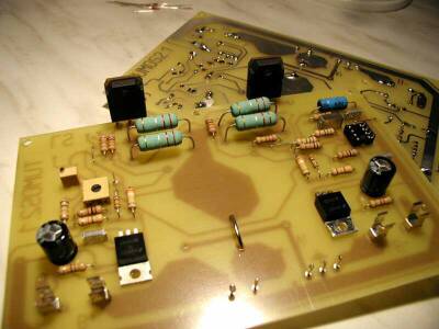
The PCB makes the construction much simpler as it is just screwed under 90 degrees at the
heatsink .... Just check the images above and below !
For interested people, the PCB's are available at cost. See the sales page ...Pleas bare in mind, I am not a shop, so there
is no inventory or so. Only on subscription I will have PCB's produced.
Control / Front Panel:
Big name for this simple input section, ahem.... But never the less, you need one, don't
you?? In this case I made it switchable as low amp and direct amp. Not mandatory of
course, but why not?? It gives you the option to have a sound check with the full
bandwidth of the amp....
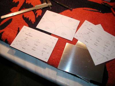
I used the proven method of the "first draw on paper, stick it on the frontpanel and than drill the holes" method as you can see above, the components are just hard wired at the back. See no expensive ALPS or something ??? Absolutely right, I wanted to start this project with relatively simple components, don' feel ever blocked to spend some more money and try for your self if you like the result. For the range to max 250Hz I doubt you will notice too much difference.... and in the "direct" position, there is no potentiometer in the way, isn't it?
Power Supply:
One of the design criteria was to have an as clean as possible Supply Voltage. The normal
setup with rectifier diodes and than 2 times a 4.700uF capacitor is technically enough,
but the big problem here is the spikes and HF noise induced by the switching of the diodes
and the fact that there is hardly any filtering. I decided to do the "overkill"
Routine and use large RC filters and fast switching Diodes like the BYW80-200.

Above image shows the very simple Circuit, the 2 RC networks are very efficient in filtering the HF noise away as well the first harmonics on the 100Hz ripple left over. The Scope image below shows how good this already works: the full scale is 10mV ( compare this with the many Volts of ripple in commercial designs!! ), so the final 100Hz ripple is only 4mV and the 200Hz harmonic is already 20dB LOWER.
OK, there is some higher frequency stuff and this MIGHT influence the high frequencies in the music signal a bit, so (I did not try this yet !! will do for sure..) there is an option of making the last section a (Tube like) LC section. Thanks to the huge size of the Capacitors, a simple (loudspeaker type) ferrite coil of 22mH will do. One with 1 Ohm resistance will be fine as this will damp the Fc even better....
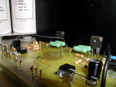
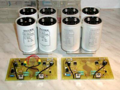
 At the right a nice picture of the Filter
module and the PCB's..... Don't stick too much on the 33.000 uF value. I just happened to
be able to get these from an EBAY Auction !! Most values will do fine, al though I would
recommend not to go below 10.000 uF each....
At the right a nice picture of the Filter
module and the PCB's..... Don't stick too much on the 33.000 uF value. I just happened to
be able to get these from an EBAY Auction !! Most values will do fine, al though I would
recommend not to go below 10.000 uF each....
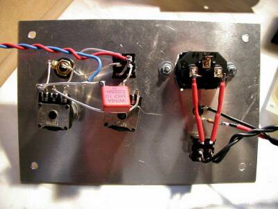
Construction of the TUMOS:
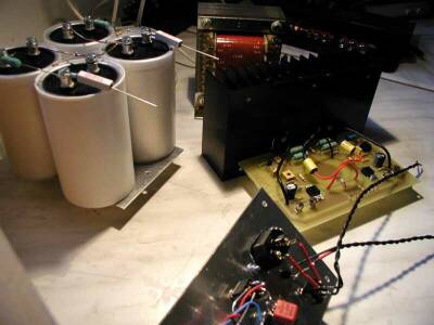
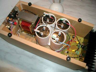
Big deal eh? The chassis below is just a simple and fast test chassis. I have ordered nice
black anodized aluminum profile chassis, but there was some delivery time on it. Never the
less, you can easily recognize the modular setup: Frontpanel, Transformer, Filter and
PCB/Heatsink. All hard wired together with silver wire of course. In the Heatsink I tapped
M3 windings for easy assembly with the MOSFET's Of course a simple L profile can be used
as well. Easier to mount the PCB of course.....
 At the right the TUMOS in action, heavy duty
burn in in my "Laboratory" The TUMOS needed approximately 3-4 day to come to its
best performance....
At the right the TUMOS in action, heavy duty
burn in in my "Laboratory" The TUMOS needed approximately 3-4 day to come to its
best performance....
The most important part: How
does it SOUND ????
As mentioned before, the TUMOS was intended to work to max 250Hz. Never the less I
wanted to listen to this very cheap amp and set some kind of reference related to my
SE amps. Bit self pleasing thing, like "look how good the Golidav's are" ....
OK, After a few days burn in the serious listening started and I was totally shocked. This
sounded VERY GOOD, much better than expected, I still had some idea how my old 300B
SE amps were sounding compared with the Golidav and this was clearly better. In this case
I switched from one amp to the other and was a bit depressed in the first place...
"do you know how much these Golidav's had cost compared to the TUMOS?" I just
didn't want the TUMOS to sound so good, psychologically correct I think, haha !! I stopped
the listening sessions, I needed a third amplifier to make a kind of 3 point measurement.
Lucky for me, Audiofriend Gydo just finished his SE amps and had no problem lending me his MUPP amplifier. This was a good choice, as the MUPP is some what different and less High End as the Golidav type of amplifiers; it is a Push Pull amp with normal Output transformer (so no exotic Amorphe), Solid state Power supply, but still MU stage drivers. A very nice sounding mid/upper class Tube amplifier. After warming up all amps (TUMOS needs max 15 minutes, the tubies half an hour...) I started listening, SACD; Vinyl all kind of music, pop, classic and typical "high end jazz-stuff". The loudspeakers were a test version of a 2 way system with the Thiel ceramic units C79 and C12. Very neutral open sound character. This loudspeaker goes to max 200 Hz in the lows, so I used an active subwoofer for the bass. Therefore no judgement on the low frequencies. Although I expect that TUMOS will be more or less equal to the MUPP, which normally scores a bit better (5-10 points than the Golidav. A matter of basic principle...
I can make a long story, but prefer to put things in a small table, The Golidav is always the reference with 100 points. 2-5 points means a small just noticeable difference. 5-10 points means clear improvement over the other. 10-20 points means different class of music reproduction.20-50 points means a completely different world...
I know this is always a bit subjective, but a long story with fuzzy descriptions does not help either, eh?
| Sound Parameter | Golidav | MUPP | TUMOS |
| Low level Detail | Extreme low level details, good timbre, small echoes | Plays one level of detail higher. or should I say lower?? | like Golidav, but a bit less timbre, echoes very nice |
| Points | 100 | 85 | 93 |
| Mids | Very clear, transparent, power full | Voices are clean, very neutral balance, high fluency, less powerful, | Mids are extremely clean!! very neutral and VERY homogeneous, extremely fluent ! |
| Points | 100 | 96 | 105 |
| Highs | Extreme detail, very smooth, very silky | Very close to Golidav | fresh, sparkling and transparent but not as silky and detailed as the others. This is clearly the only point where TUMOS "loose" |
| Points | 100 | 98 | 80 |
| Dynamics | Very dynamic | bit laid back | Very dynamic, just below Golidav |
| Points | 100 | 90 | 98 |
| Soundstage | Open, spatial, Huge Soundstage, great pinpoint | Less open, pin point ok, limited soundstage | Open, good pin point and wide&deep soundstage |
| Points | 100 | 90 | 95 |
Conclusions ??
TUMOS is the ABSOLUTE HIT in price/performance. This amplifier sounds better than a lot of Tube amps I have heard before and is very close to the Golidav, clearly wins from the MUPP in regard to most character points. The only point where the TUMOS is a bit behind are the highs. Don't take this too serious, A transistor amplifier with the typical sharp sssss would score less than 50 points here. My old SE amps with JJ 300B tubes would also not score more than 80 points here by the way. The highs are indeed very nice, but just miss the magic from the MUPP and GOLIDAV who are both very very nice in that particular area. I will tweak a bit around with the power supply and the current limiting transistors, to see, if we can improve this part of TUMOS.
Basic
Measurements and Specifications:
The boring stuff (for most people...)
A 10kHz square wave at 6Ohm
load. Green is input, Yellow is output, Very clean, no overshoot etc. Easy to calculate
the Output impedance...
FFT from the same output. No comment,
distortion is below every thing you need (0.3%)
FFT from the Power Supply. Only 4mV
100Hz ripple on top of the 25 Volt DC. The d2 (200Hz) ripple component is already 20dB
lower. Some HF noise, but may be a LC design can cut this out as well. Need to try this
and listen to the effect of the high frequencies.......
Main Specifications:
| Output Power | 12 Watt Class A into 6 Ohm / 35 Watt AB into 6 Ohm |
| Dampingfactor (8Ohm) | 11 |
| Bandwidth | To be set by Gate Resistors. Current version 400kHz |
| Distortion | Less than 0.3% |
| Building Cost | Aprox 150 Euro per Channel....... (less when you use EBAY:-) |
Different Applications for
TUMOS:
If you just let your fantasy carry a little bit away with you, there is unlimited
applications for this TUMOS design. The low price for building a set makes it also worth
while to do so.... Lets freewheel a bit:
Conclusions??? Sometimes things just fall into your lap.... With TUMOS I feel exactly this way. It was not intended to create something good sounding like this in the first place, but by keeping things simple and using the right design principles TUMOS saw the light with an UNBEATABLE COST/PERFORMANCE ratio.
Happy Listening and Building !!!!
Doede Douma
IMPORTANT: The information provided on this page is intended as guide for DIY activities and therefore free to copy and or publish. If any one wishes to use any of the information from my WEB site, please make sure to refer and footnote to my URL Link as source! Doede Douma