 Actually the basic filter is known now, Just have a look at the
right and you recognize the filter sections described above. The only problem is, what
values the components should have ????
Actually the basic filter is known now, Just have a look at the
right and you recognize the filter sections described above. The only problem is, what
values the components should have ????Updated:
08-Dez-06
Go Straight to the
Jan 11 Final Update !!
Introduction
Probably unnecessary to say, but the filter is the second step to come to the final result. Also the one where you do the most experimenting !! (and measuring....). Why? Well, I did not buy a huge number of speaker chassis, nor will I construct many enclosures; too much work and too costly. Just using a filter from "the book" is of course the biggest mistake you can make. They all presume a speaker to be a 8 or 4 Ohm resistor and every coil and capacitors to be perfect. Nooo way !! But tweaking the speaker box to perfection with filter is a great challenge ofcourse. Sure I will use all the nice tools I have at hand now, to design this filter step by step. Let me take you on a hopefully interesting and educational journey (instead of just publishing the final result, stating that after weeks of work, this was the best result, boooooooringgggg) ---------->
Design Considerations:
What are the basic requirements of my filter? lets have a step by step look at what I want / need:
Actually the basic filter is known now, Just have a look at the
right and you recognize the filter sections described above. The only problem is, what
values the components should have ????
Well there is only one way to success in DIY, measuring, measuring, measuring, measuring.....
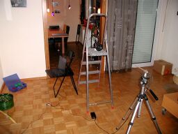
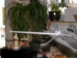
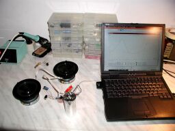
First I have built up this test
site............ You can see the Notebook with the soundcard and the microphone I built
for this purpose. The Tripod is extremely handy here, to position the microphone exactly
at 1 meter (every thing is calibrated for SPL in dB !!!! ) and exactly straight in front
of the speaker. The units are positioned on a plate of damping material. The reflections
are now reduced to a minimum. Hobby box is calculating from the computerized test tone all
necessary graphs now.
From the Frequency response curve I drew a few conclusions:
# LMS: terrible peek
round 8kHz, must be reduced strongly
# LMS: roll off after 2kHz, may be this is a good point to start filtering. let
yourself not mislead by 1kHz. This is because the unit is open
# the tweeter has some lift at the high range. will see later on if this
needs special treatment. For now I think it will be ok. The lower SPL below 5kHz will be
lifted as soon as the unit is damped and in a closed box. To start I choose a cross over
of 2k4 kHz.
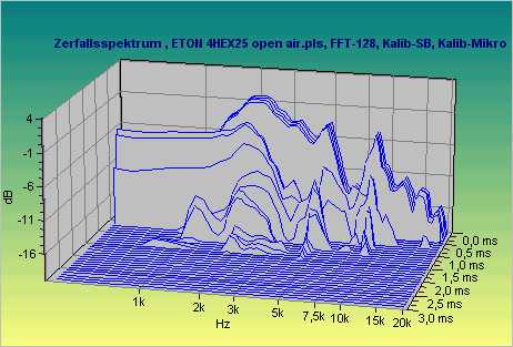
The Waterfall diagram shows and
confirms, that the LMS is a very fast and well controlled chassis.
The peek at 8kHz is bad, but we will take care of this by the LCR network, tuned at
8kHz
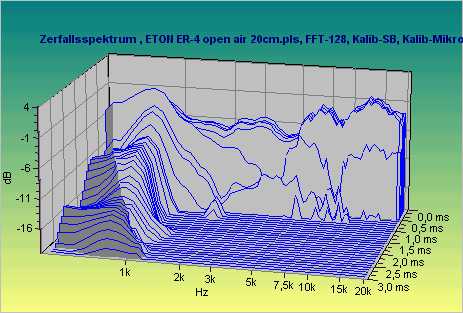
The waterfall curve of the ER4 is a
beauty !!! Fast, no ringing, very good.
The long smooth resonance below 1kHz is not sharp and well below the corner freq. I
picked.
Very promising !!
What's next ??? Impedance of both units!! With HobbyBox, this is a piece of Cake ! Fully automatic and precise. As an extra the Thiele and Small parameters are calculated............ Pffff this program is worth every €uro.......
 What's next ??? Impedance of the units!! Right the ER4, below the
LMS
What's next ??? Impedance of the units!! Right the ER4, below the
LMS
There is no work to be done on the ER4, IT IS TRULY A RESISTOR !!!!! Therefore I pick C1 on 14uF to start with and L1 will be between 0,4 and 1 mH. The higher the value the more the filter reacts as a 6dB round the Fc. The lower the L1 is, the more it goes towards a 12dB filter. No conclusion yet........ this will be done by experimenting and measuring the frequency response of the whole speakerbox later on. And listening of course.
OK, now the tough one: the LMS.........
First of all, we need to
compensate the Inductance of the voice coil, to present a "resistor" to the
Filter Choke L2
R1 must be so, that the curve will continue at its minimum. There is some effect of
parallel resistance, so I picked 3E9 (on hand)
C2 was varied so long, till the black curve started to be flat. Really it is DEAD
EASY with this equipment. If you use a network from a magazine, it will NOT be so good as
this "Hand selected and tweaked result" . Oh yeah, the value: 20 uF. As L2,
which defines the Fc for the LMS, "sees" a "resistor" of 3 Ohm, the
calculated value will be 270uH. Another value revealed..... We are making progress........
still there? go to the next graph ---->
The basic principal of a series LCR network is, that in a certain bandwidth the resistance of the network is "zero". In this area, the network presents the resistor. This resistor needs to be low, so that in combination with L2 a new low pass is generated, but now at FAR LOWER Fc !! Therefore the sound reduction will be over proportionally large. And is just what we want at this peeking point of the LMS. Just check the graph and you will see that the network reduces the LMS impedance round this point to almost 1 Ohm. This will ensure good damping. See also that till 2kHz the effect is almost zero?? I will spare you the calculation, but the components are now known for this section: 2.2 Ohm, 4.7 uF and 100uH.
For the real freaks, the formulas are:
Fc = 0.16 * SQRT [1 /
(LC)]
B = 0.16 * R/L
B = how wide the "dip" is at -3dB points
!
What is this? The impedance the
Amplifier is seeing.
Flat after 150 Hz (exactly what my Tube amp likes !!!)
A very minor peek of 11 Ohm.
Well, that wasn't too difficult, eh ??
ALL Values are know now. This is the kick off version of the Filter unit
For those who think we are ready now, I have some disappointing message. WE HAVE JUST BEGAN !! The very Next step will be:
Measurements in the Loudspeaker enclosure and tweaking of the filter:
Indeed: a bit late, but better late than never !!!!
UPDATE Jan 11th 2003:
The filter which is described above was the first "theoretical" filter. Of course I built this one first to do initial testing. The Sound as well the measurements showed that the middle frequencies were totally over pronounced !!! First I did not understand why this was, but I found out (through the Internet) that this was caused by the so called Baffle Diffraction Step.... (Click on the link for more technical details) This text is originally from Jason M. Neal, so all honors go to him!! Basically it says, that if a loudspeaker is mounted on a small baffle, from a certain frequency down wards, the energy is also radiated to the back, as the wavelength becomes longer than the width of the enclosure....
You can see that clearly in the measurement below:
 The Black trace is the speaker without any filter in the
speaker enclosure. Clearly the 6dB uplift in the mid range. The only way
to compensate this, is to use a much larger ( !! ) Coil than the straight
calculations tell you !!! In this case I had to increase to 0,68 mH (compared to the .27mH
from the first design) to compensate and get a flat response. This is the RED trace. The
green trace is the speaker with the 0,27mH for comparison. By the way, the effect of the
LCR circuit is clearly visible
The Black trace is the speaker without any filter in the
speaker enclosure. Clearly the 6dB uplift in the mid range. The only way
to compensate this, is to use a much larger ( !! ) Coil than the straight
calculations tell you !!! In this case I had to increase to 0,68 mH (compared to the .27mH
from the first design) to compensate and get a flat response. This is the RED trace. The
green trace is the speaker with the 0,27mH for comparison. By the way, the effect of the
LCR circuit is clearly visible
Below a picture of the Filter board....... as it emerged....
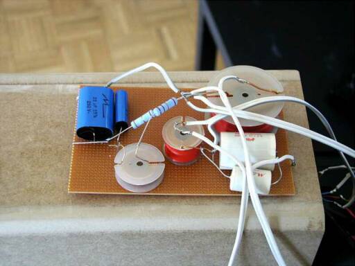
Below is the Filter as
it turned out to be the final one. Please NOTE that the RED wire from the ER-4 is the
MINUS Pole...... Bit dumb from Eton, isn't it????
Below is the final composition of the 2 speaker units and there combined result....
For me, the most important point I learned, was that WITHOUT the measuring equipment it would have been IMPOSSIBLE to get the right filter designed. Another proof for my never ending preaching on T&M equipment.......
Oh, yes, the value of the Capacitors for the tweeter was reduced from 14uF to 12 uF, purely a matter of taste......
Happy Listening and Building !!!!
Doede Douma
IMPORTANT: The information provided on this page is intended as guide for DIY activities and therefore free to copy and or publish. If any one wishes to use any of the information from my WEB site, please make sure to refer and footnote to my URL Link as source! Doede Douma