Updated:
02-Jan-06
DDDAC 1543, Circuit Description
Introduction:
This page will describe how the circuit
basically functions. I will not go in extreme details, but just "walk you
through" the basic elements of the DDDAC1543, so you can follow what I have been
doing.....
It might proof to be useful if you open the documents first, save or print them and have them at hand to keep an eye on the overall circuit.
CLICK HERE for high resolution Circuit on screen OR CLICK HERE for PDF high resolution Circuit (updated version 2.2)
Digital Inputs:
Clear we need a S/P-DIF input :-) This
is straight cook-book: To make things as universal as possible I took both optical and
cinch input. If you want to make things even nicer, you could put a 1:1 transformer at the
input for the coax, but I have not done this. May be I try later if it really makes a
difference.... The optical input is the welknown Toshiba module. Please note that if you
use a Mains Power supply it may be useful to put a RC network before the V+ of the
TORX176.

Receiver:
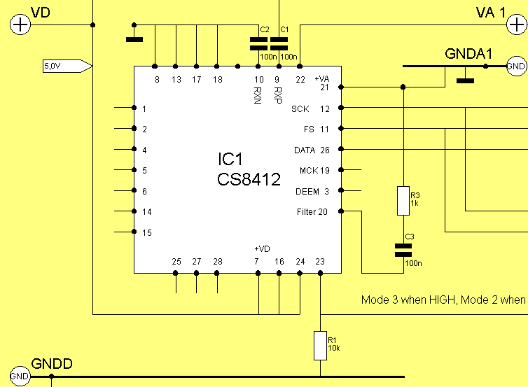
Although a CS8412 is chosen, every
receiver which can output I2S signals is suitable. Never the less, this one is easy
available through out the world, it is still "through-hole" where the rest of
the world seems to be SMD.... and relatively cheap (although the most expensive component
in this project !!!). The receiver has the option to work with 2 supplies. One for the
digital part and one for the VCO. To go for sure I keep the 2 separated. Even in the
probably never used position of S/P-DIF clock, I think it is fair to make it still ok....
The datasheet tells us, that in Mode 2 we have I2S signal structure and the clock is being
reconstructed from the incoming signal. This is selected by the pins M0-4. However, if pin
23 is selected HIGH, the 2 signals FS and SCK are switched as inputsignal, so we can use
the external clock..... The De-emphasize is not used as CD's with this old fashioned
system most likely are not in your collection. Otherwise use the normal output of your
CD-Player I would like to suggest. The R-C network is for the VCO. Some people say it is
even better to put a 3300pF C from pin 20 to ground, so feel free. On the PCB there is
space both with holes as with SMD pads.... From pin 26 finally the serial data is
led to the DAC's inputs. The 2 clocking signals controls the timing: SCK is the bit clock,
running at 64Fs and Fs is of course the word clock, clocking each complete sample every
44.1 kHz

Re-Clocking:
The 2 key signals to clock the data
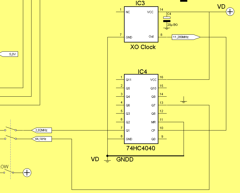
around the receiver and DAC are the 64Fs and Fs. These can be easily derived from an
11.289Mhz clock by dividing by 4 and and 256..... The 74HC4040 does exactly what we
need here... Q0 is the first divide-by-2 section and every next "Qn" will
divide by another 2. Therefore we tap the signals at Q1 and Q7. The 3 pole switch makes
now the selection possible between internal and external clock signals as by the 3rd pole
the CS8412 is switched between mode 2 and 3.....

DAC:
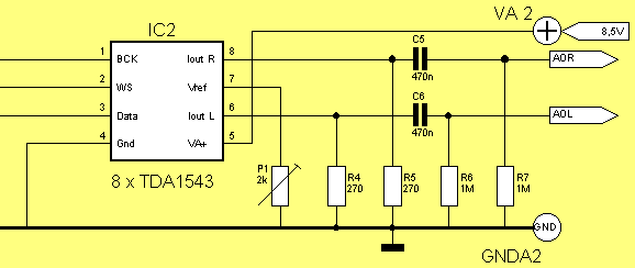
The DAC is receiving the serial signals
and store them in registers. At every Fs the value of the sample is converted into a
current at the outputpins 6 and 8 . How this mathematically works is described detailed in
the datasheet. Important is, that by changing the Voltage reference at pin 7 the internal
balance and linearity of the DAC is kind of pre-set. In fact the voltage at pin 7 is
defining the internal current source. There are clear measurable and audible differences
!!! I found out, by measuring and listening, that the best results were obtained
when the Rload resistor is 2 times the Rref... Or (this is the same, but easy to measure)
the Output DC voltage over Rload is twice the Vref. Also the best results were got when
the DC at the output is slightly below half of VA2........
In summary: per DAC, the Rload should be round 2k2 and the Rref 1k5. If you use "n" DAC's just divide these values by "n". In my case with 8 DAC's it is 2k2 / 8 = 270 Ohm (next practical value) If you now use a trimmer for R ref, you can even trim the DAC individually by use of a FFT analyzer or just with your EARS. Works pretty fine. Of course AFTER you chosen or trimmed the Voltage VA2. This is less critical and works fine between 8.0 and 8.5 Volt. It works with lower voltages as well, but you need to re-trim the Ref and Rload as well !! Furthermore, the DAC seems to sound best at the mentioned voltages. You can measure differences in k2 as well.....
Due to the DC at the outputs, we need 2 capacitors to lead the signal to the next stage..... I used Auri-Cap's, but feel free to take your personal favorites :-)

Power Supply:
Some listening tests showed that using a
normal Led Battery was giving better results compared with a typical regulated power
supply. I am not arguing that an extremely complex super low noise power supply will
have the same drawback, but in that case a Battery seems again very uncomplicated to
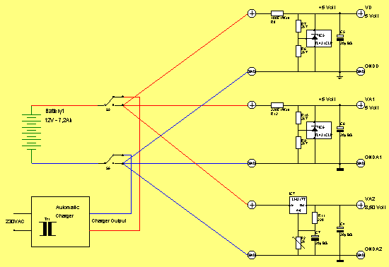
me.... With the 7.2 Ah version I use, I can play almost 15 hours at a time. To be honest,
I normally don't ..... Using a 2-pole switch as on/off switch cleverly, the Battery
is connected to a standard Battery charger you can buy in every Electronics shop for less
money you could build it yourself. I use a fully automatic one, so it can stay connected
without limitations for longer time. Actually it keeps the Battery "fresh".
Cost? 29 Euro....
Ok, now we need to make 5 Volt from the 12Volt Supply. What I have done is separating the 3 major Supply Points (Receiver Digital & Analogue and the DAC). I have not done A-B tests, but never the less it appeared no bad idea, as I could measure otherwise some HF stuff over the power supply line, which might cause some influence..... Through the low impedance of the Battery, the 3 are effectively separated now. The use of the SHUNT regulator TL431 for the receiver might improve this even further. For reasons of supply current (500mA) I used a nicely cooled LT1085, which allows very precise trimming of the VA2 as well. On the PCB a 20 turn spindle let you choose your supply voltage without any problems...... For decoupling I used 20uF Black Gates. Why? I have a box full, so they were on hand. Feel free (again) to take your favorite or what you have on hand....... No magic, no rocket science...... BUT do not make the value BELOW 5uF as this is a MUST, not to let the TL431 oscillate !!!
Click the Image for a
high resolution version on screen

Happy Listening and Building !!!!
Doede Douma
IMPORTANT: The information provided on this page is intended as guide for DIY activities and therefore free to copy and or publish. If any one wishes to use any of the information from my WEB site, please make sure to refer and footnote to my URL Link as source! Doede Douma