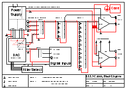
The DDDAC 2000 consists of the following functional blocks:
Updated:
24-Jan-01
Block Diagram: overall overview how this DAC/Line Amp is set up
It is recommended to download first the PDF Document DDDAC1.pdf with the schematics.
For pictures of all the parts please see the Technical Backgrounds Section and Picture Galery

The DDDAC 2000 consists of the following
functional blocks:
Power Supply
The power supply unit is providing separated regulated supply voltages for
the digital sections, the analog sections and the tube stage. All over-designed to keep
noise low and to keep the regulating part as much as possible out of the signal path
Digital Inputs
I have chosen to have 2 optical inputs and 1 coax input. Of course the is no limit
and this can be adjusted to any personal circumstances. I have not been able to tell the
audible differences, in spite of lots of articles where the differences have been
noticed.... Make your own choice I would say!! Switch Sd selects the digital source.
Filter Select Section
Just a bunch of switches, enabling you to select the different filter options and
bit width selection from the filter chips. In the version 2.0 this section is left out and
the selections are made on the chip connections itself
DAC unit
I have build a special version where experiments can be done with different
combinations of receivers (the "old" CS8412 and "new" CS8420 with
asynchrone re-sampling) and digital filter chips (the Burr Brown DF1704 and NPC SM5842PT).
By simply switching the data lines from one chip to another, it is easy to set up any of
the 4 possible combinations of the 2 receivers and 2 digital filters.
Analog Section, Inputs and
Volume control
Here comes the line amp nature of the project. The analog output of the DAC section
(after the transformers) is one of the possible analog source options. After the selection
I have been using a 2 stage Volume control. The first one selects 0dB, -20dB, -40dB and
-60dB. The second stage delivers 12 steps of aprox 2dB. This was done because 12 step
switches are much cheaper than 12 step.... Of course anything can be done here, from cheap
potentiometers to 500$ golden 24 steps ladder configurations..... again. make your own
choice!!
Tube Stage
I have chosen for a so called MU-stage here. Somewhat more complex than a straight
grounded cathode or SRPP, but some nice advantages like full MU gain, high input impedance
and very low output impedance, thus capable of driving long cables to the mono blocks.
Grounding
3 different grounds are used: Digital ground, Analog ground for the DAC and the
analog ground from the Line stage. By doing so, I reduce the possibility of ground noise
and current interference between the 3 different circuits
IMPORTANT: The information provided on this page is intended as guide for DIY activities and therefore free to copy and or publish. If any one wishes to use any of the information from my WEB site, please make sure to refer and footnote to my URL Link as source! Doede Douma