Updated:
14-Jan-09 17:08
Doede's Audio Tweaks...
Tweak of the week: A
simple GENERAL PURPOSE PCB solution for Voltage and Current Sources
Most of us are using DC to heat the
small signal tubes and the Penthodes in the MU stage. For the real DHT lovers, a current
source is an absolute MUST !! A real good current source is also fed by a regulated
voltage already. So for example, for a Stereo Line amp with DHT's you already need 2
Voltage sources and 2 current sources. Most of us does it in hard wiring or on a simple
piece of general purpose PCB with a raster of holes and Soldering islands. No problem, can
be done and it works just fine...............
 BUT: My opinion was that
it does not LOOK neat and it is a lot of work, specially with a RIAA / Line amp and MU
stages.... Would it not be easy, if you could just grab in the drawer and take out a
simple Module, just like you take a component??? Ohhhh yeeaaaa, that would be easy, eh ???
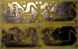
Solution was on hand of course; I made a simple general purpose PCB solution. No ROCKETS
SCIENCE !!!! just an industrial quality PCB with 2 Voltage sources and 2 Current sources:
BUT: My opinion was that
it does not LOOK neat and it is a lot of work, specially with a RIAA / Line amp and MU
stages.... Would it not be easy, if you could just grab in the drawer and take out a
simple Module, just like you take a component??? Ohhhh yeeaaaa, that would be easy, eh ???
Solution was on hand of course; I made a simple general purpose PCB solution. No ROCKETS
SCIENCE !!!! just an industrial quality PCB with 2 Voltage sources and 2 Current sources:
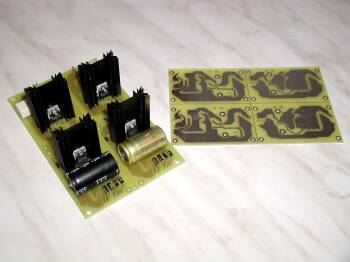
You can use it in one piece for
Stereo; just connect the Voltage Output to the Current Source Input on the PCB Or cut the
whole thing in 2 or 4 pieces, Just what YOU need for your application !!!
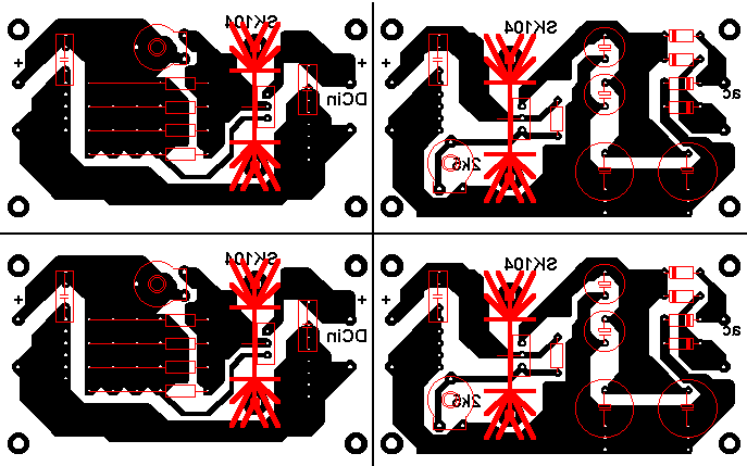
 The next 2 Images are
showing in more detail how the PCB's can be used. There is enough room (and drilled holes
!!!) for several different types resistors and Capacitors, making it really general
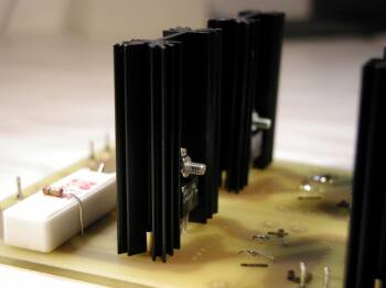
purpose. The cooling element is the very standard SK104. You can get these in 3 sizes,
25mm 38mm and 50mm. All with different K/W ratio. The interesting thing is, that you can
SOLDER this element on the PCB !!! very easy and solid construction is the result.......
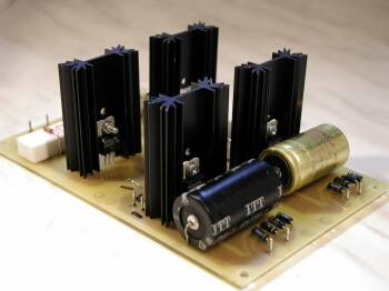
The next 2 Images are
showing in more detail how the PCB's can be used. There is enough room (and drilled holes
!!!) for several different types resistors and Capacitors, making it really general
purpose. The cooling element is the very standard SK104. You can get these in 3 sizes,
25mm 38mm and 50mm. All with different K/W ratio. The interesting thing is, that you can
SOLDER this element on the PCB !!! very easy and solid construction is the result.......
Techy
Portion.......:
I used the following
basic circuit for the Voltage and Current source:
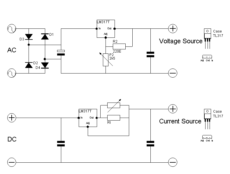
For the voltage
source, with the given values for R2 you can reach aprox 15 Volt. With R2 = 110 Ohm, you
can get 25 Volt out. Of course your input voltage needs to be (after the C minus ripple
pk-pk !!) aprox 2 Volt more than the desired Output Voltage
Do not forget that
this can consume very nicely some power !!! Example: 15 Volt DC after the C, 6.3 Volt
output at 600mA... Pd of the LM317 is now aprox (15-6.3)Volt x 0.6A = 5.22 Watt. If you
use the 50mm SK104 (10k/W) the heatsink will become almost 70 degrees !!! In this
particular case I would suggest to lower the input DC a bit...... My recommendation is,
not to heat up above 50 degrees !!!
So limit the Pd to 3Watt with the 50mm Heatsink !!!
For the current
sources the formula is very simple: Iout = 1.25 / Rl or
RI= 1.25 / Iout
Example: for a Ba Tube I need 500mA, this will result in 3.5 Volt across the filament. For
Ri the value is now: 1.25 / .5 = 2.5 Ohm. Use a 2.7 Ohm resistor and trimmer of 100 Ohm in
parallel for proper adjustment as the trimmer would read aprox 35 Ohm.... The input DC
should be at MINIMUM: 2 Volt (for the regulator) + 1.25 Volt (the current source
resistor ref voltage !!) + 3.5V (Voltage across the Filament). thus: aprox: 7
Volt.... more is ok, but you will have more power dissipation and more heat........
OK, last technical
help than: How large does the input C need to be??
Very simple, with the above you define the MINIMUM DC voltage you need and current drawn
by the load.
The ripple voltage on
the C (pk to pk) will be now Urtt[Volt] = 1.5 x Iload[mA] / C[uF]
Add this to the minimum DC, add 2 Volt for the Diode Bridge and divide by 1.4 and
you have the Transformer AC Voltage...
Example: Need 6.3 Volt at 600mA and use a C of 1000 uF. Urtt = 1.5 x 600
/ 1000 = 0.9 Volt ------>.
Ut = [6.3V (DC out) + 2V(LM317) + 1 V (ripple) + 2V (Bridge) ]/ 1.4 = 8Volt,
Best is now to use an industry standard 9 Volt AC output transformer.......
Just imagine you came
out on 9.5 Volt for a certain application.... mmmhhhh what to do??? simple increase the C
to 2.200uF, you will reduce the ripple enough to come below the 9 Volt now.... personally
use the following rule of thumb as Capacitors are cheap anyway ----->
I load |
Capacitor
|
0-100mA |
1.000
uF |
100mA
- 500mA |
2.200
uF |
500mA-
1.5 A |
4.700
uF |
For easy building up
of the PCB, below is the lay out seen from the component side...
Do you need
/ want it from the soldering side??? Just click the Image .........
Well, isn't this
just one of those nice & easy things, which makes our hobby life a bit more enjoyable
????
Can I get
these PCB's somewhere??
Yes, Just look
here
Happy Listening
and Building !!!!
Doede Douma
IMPORTANT:
The information provided on this page is intended as guide for DIY activities and
therefore free to copy and or publish. If any one wishes to use any of the information
from my WEB site, please make sure to refer and footnote to my URL Link as source! Doede
Douma